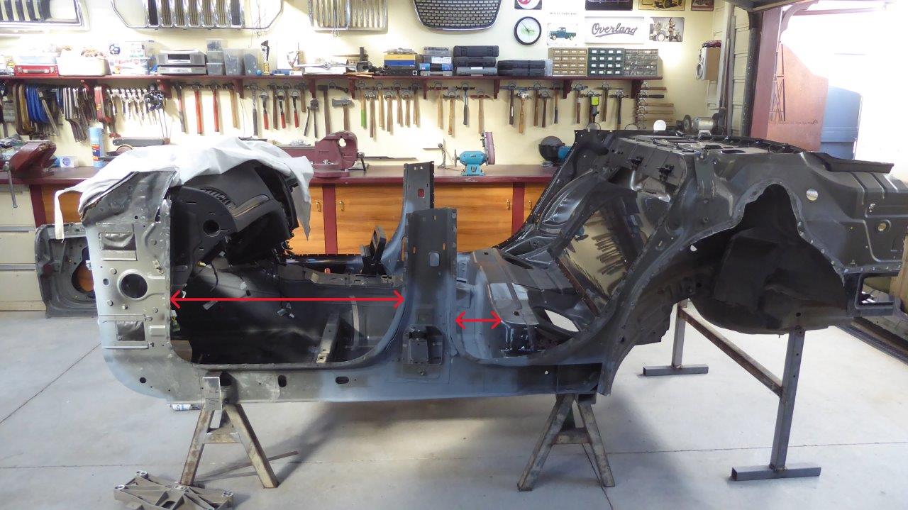
Setup the laser to get the exact distance from the rear axle centreline to the firewall on the Willys and the Chrysler 300 SRT8 donor. It was greater than I expected and was a 500mm-20" difference! This would mean that the Willys 113" wheelbase would grow to 133"! So something had to be done.
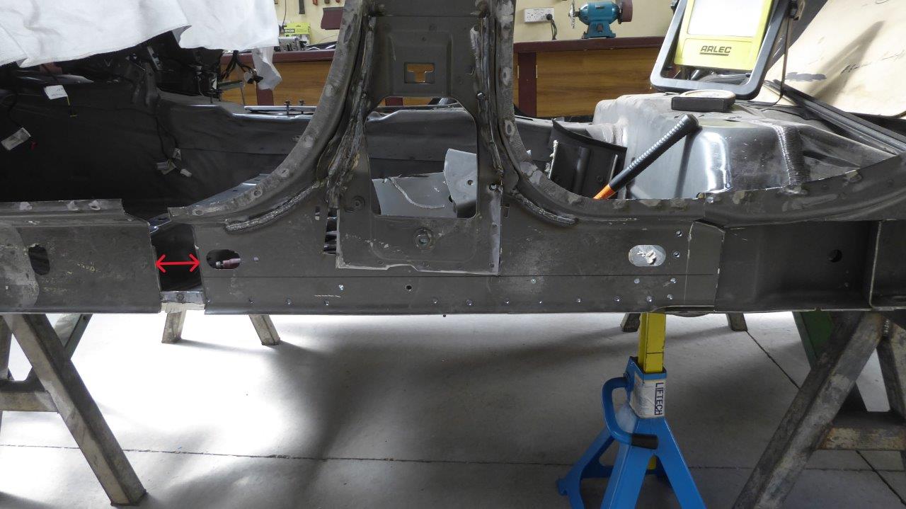
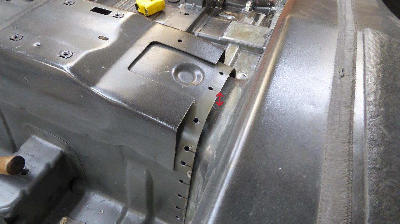
Notice the section cut out in front of the B pillar that is arrowed. That is 70mm-2.75" missing.
Then the whole B pillar was removed back to the original factory join at the seat riser.
Then all the leaning forward of the B pillar modifications was done on the other side with the same section cut free. I then removed all the calking from the end of the floor seam and marked forward from there 165mm-6.5" in different spots as the seam is not straight.
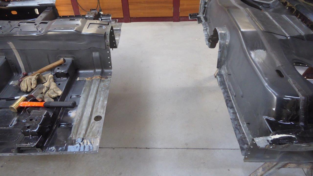
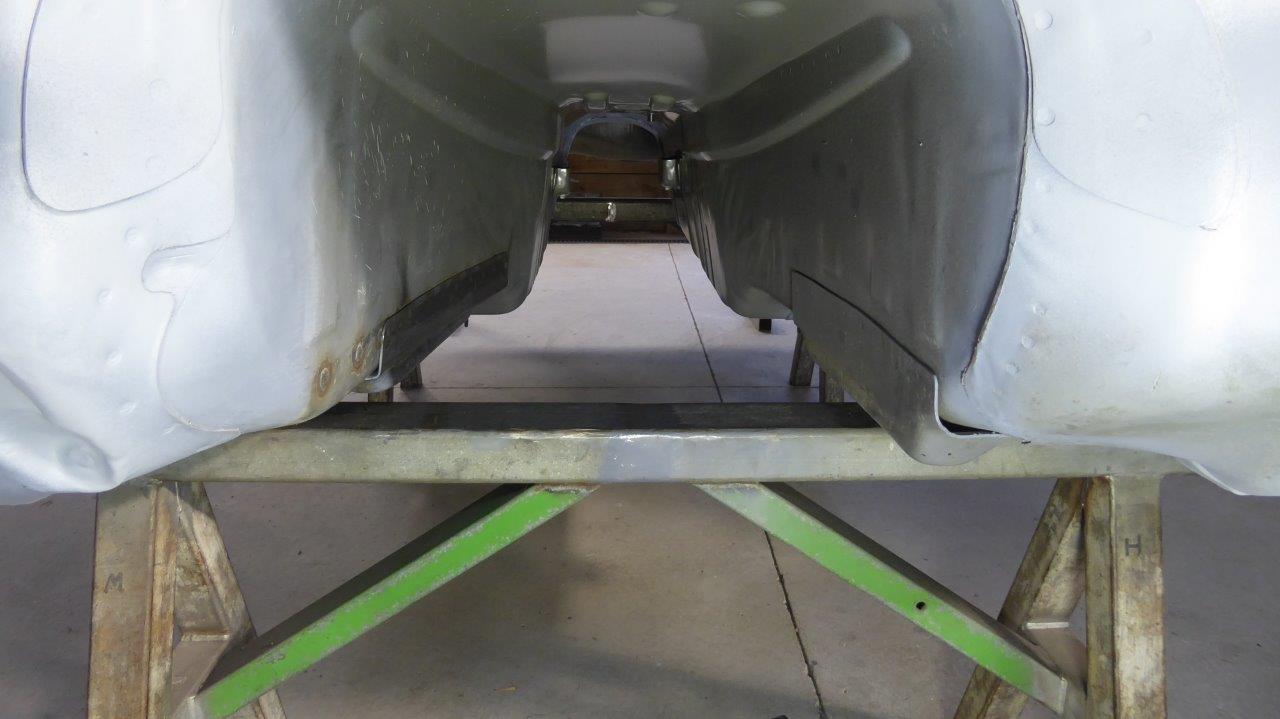
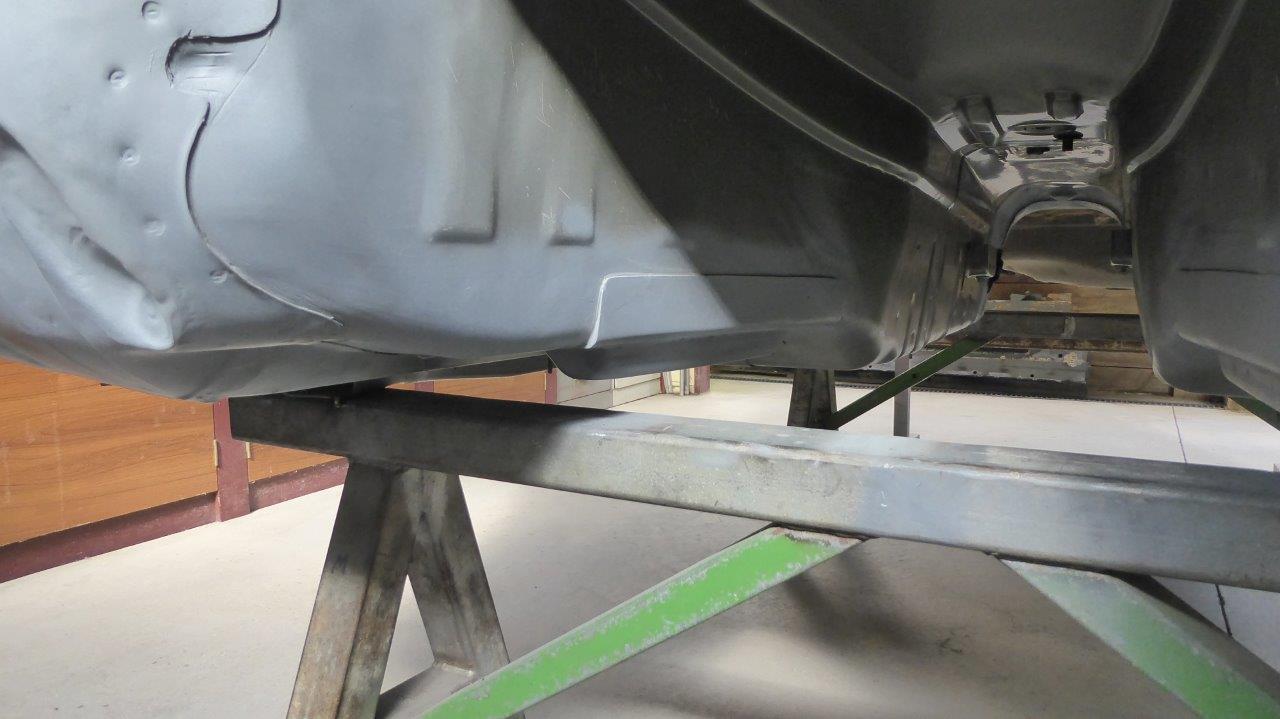
Then out came the cut off wheel and reciprocating saw to sever the shell in two!
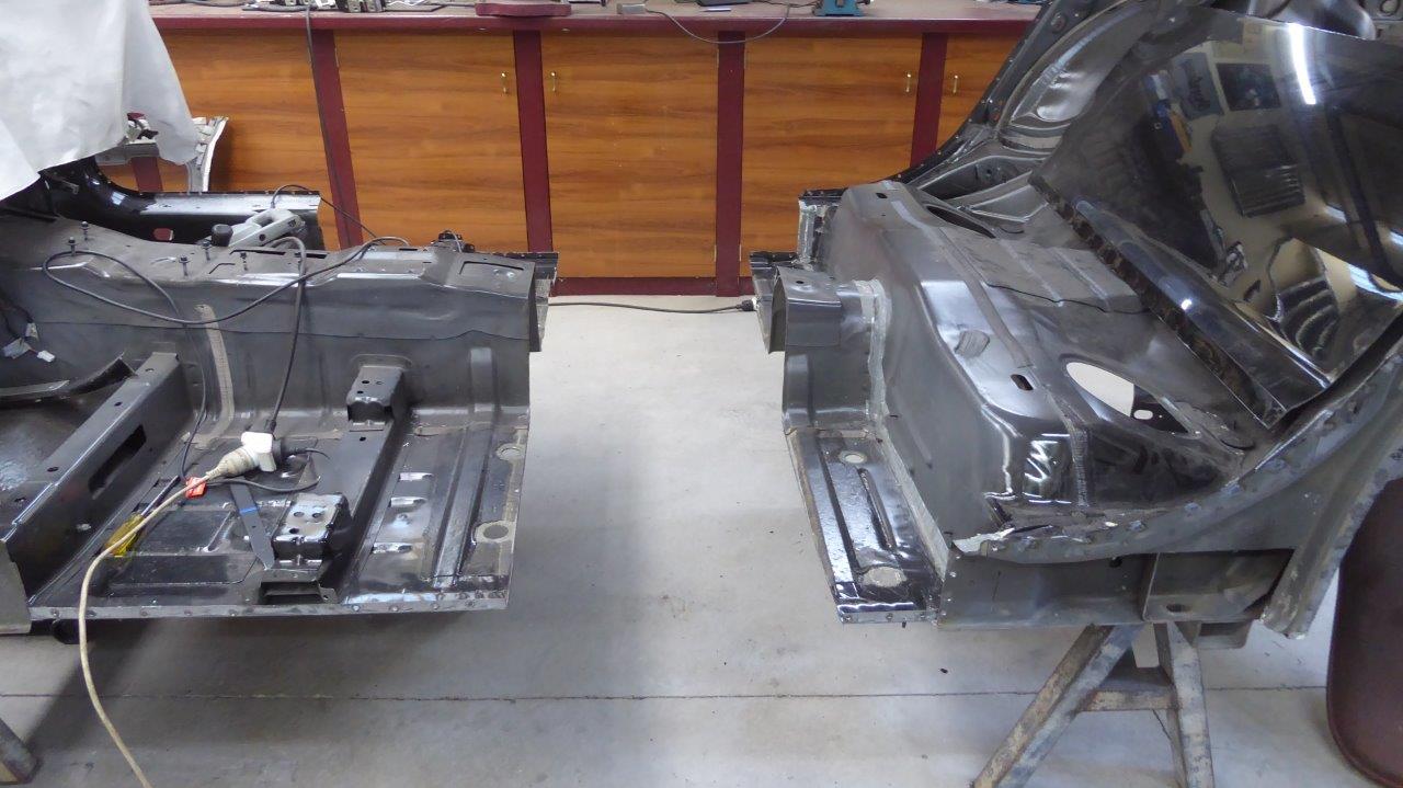
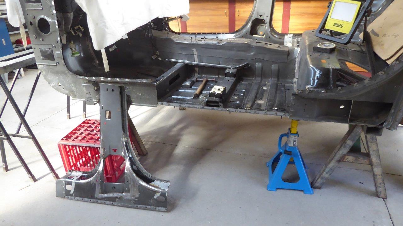
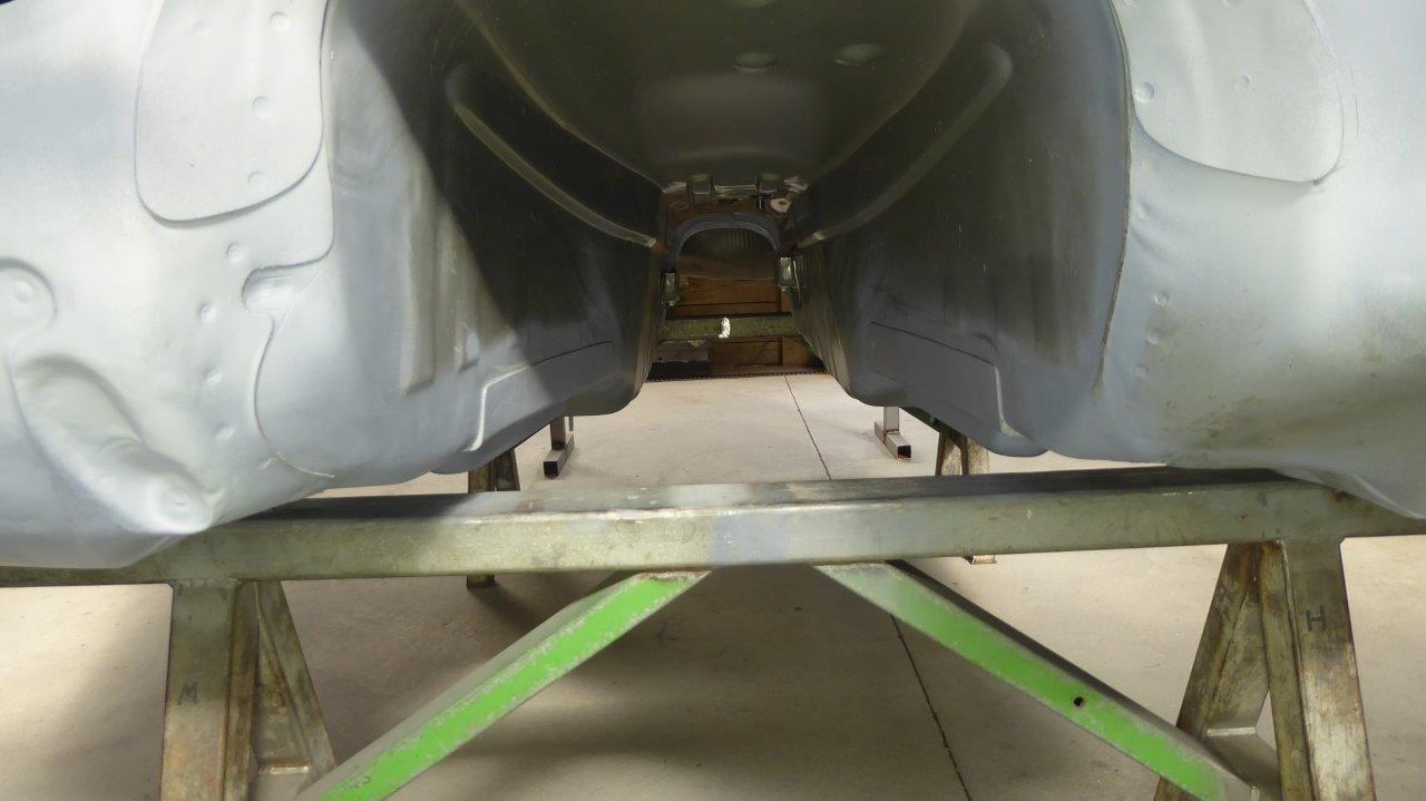
Then I rolled them apart so the next stage could begin.
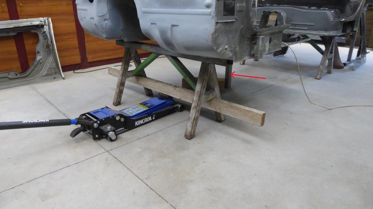
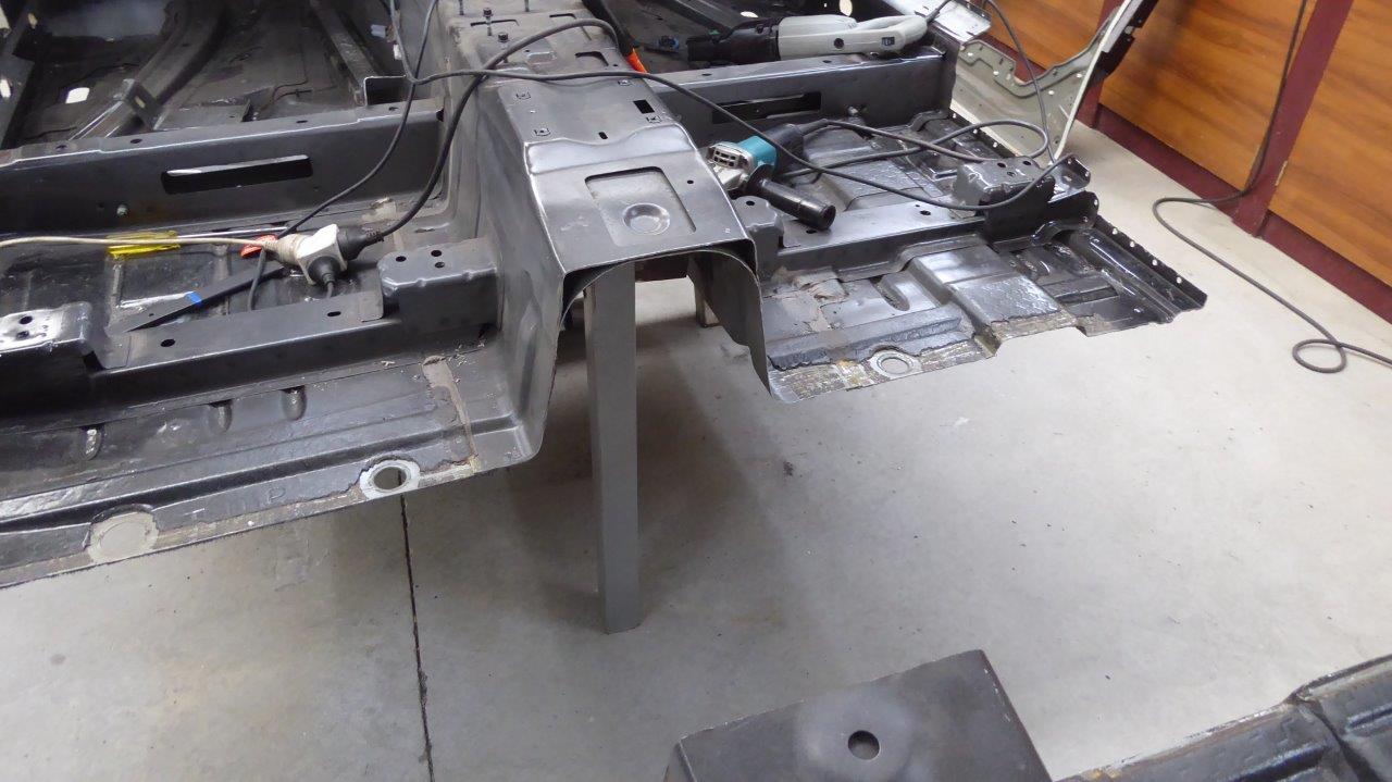
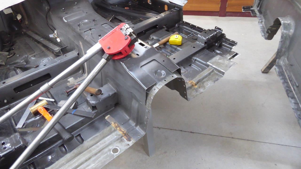
Before I cut it in two I made a support leg that bolted to the centre bearing mount inside the tunnel. It was at the exact height so alignment later would be easy and wouldn't fall after cutting the shell in two. The jack is at the balance point of the front section to make it easy to move the section around by myself.
The edge was de-burred and the assembly holes that had a dimpled edge were flattened out so they would sit flush on the seat riser flange.
Part of the excess was rough cut off, just in front of the seat riser flange, avoiding anything that had to remain attached to it.
It was then easier to remove the remainder of the floor from the flange after the spot welds were ground through with the die grinder and the seam splitter used. The tunnel was also drilled for plug welds in the original spot weld locations. The rest of the floor can be reached using my portable spot welder that I bought from a business that used to make limousines and funeral cars.
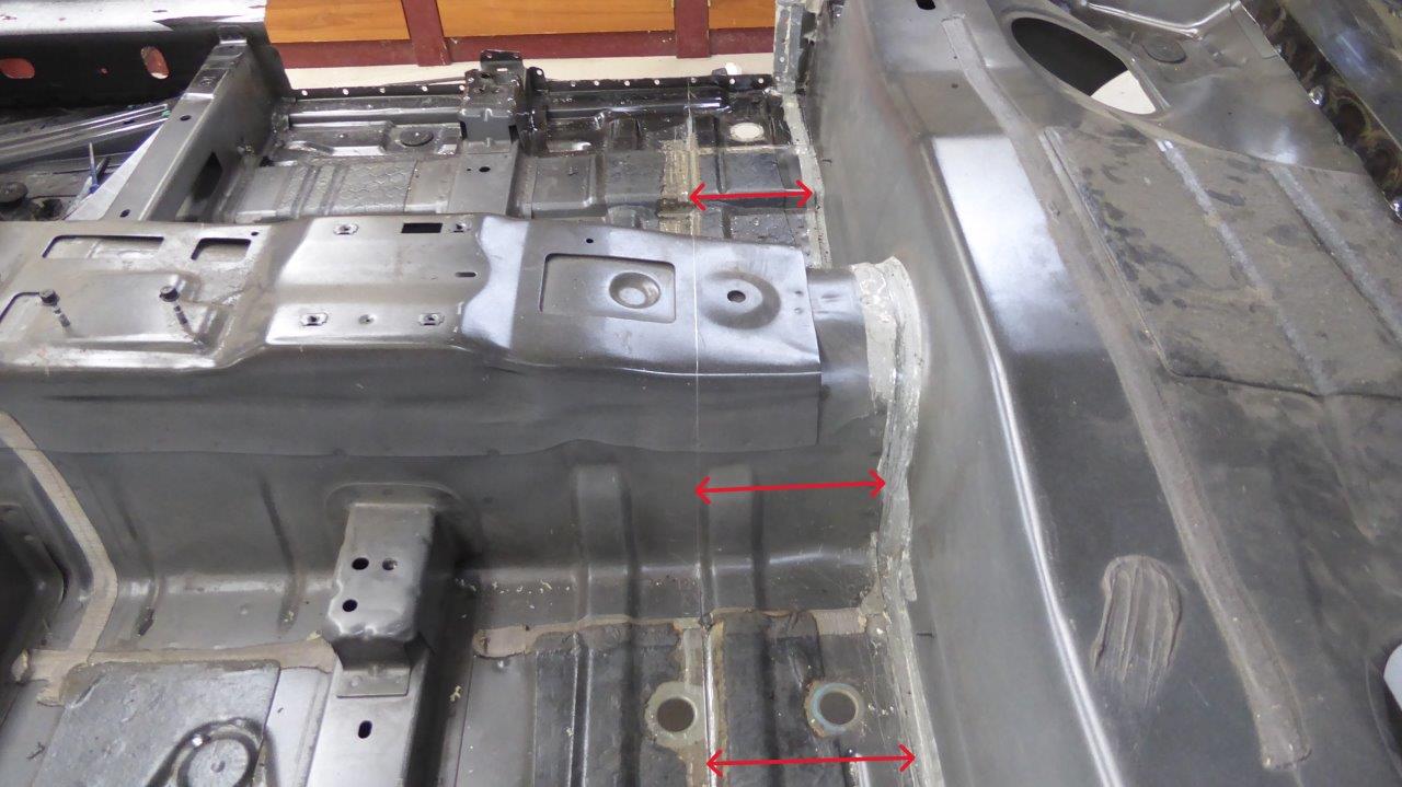
First test fit showed the height difference now between the top of the tunnel and the rear seat pan. Not unexpected given the slope in the transmission tunnel.
Wedges were cut out of the tunnel and the edge shrunk to bring down the height. The flange on the seat pan was also cut so it could be bent up to meet at the same angle.
4 reference points were measured at floor level as well as from the top of the A pillars across to the top of the C pillars, both sides, before the cutting took place. Then exactly 165mm-6.5" were deducted from these to make sure everything was true and square when it came back together. By having upper and lower points of reference, it makes sure the shell is not bending in the middle. Having the rear and front halves supported at four points also stopped this from happening. Even after welding everything back together, they were all to the millimetre. The B pillar was then welded back in 70mm-2.75" further forward and the part behind the B pillar was step flanged at the factory seam after 95mm-3.75" was removed.
Seam sealer/adhesive was added between the layers before welding them together. The factory assembly holes were also welded shut along the seam.
Etched primed to stop any rust while the build continues. Will be zinc coated and a seam sealer used later on.
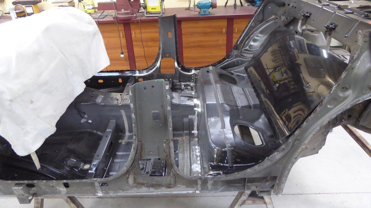
This brings the distance from the rear seat raiser to the back of the B pillar the same as our daily driver, a 2010 Jeep Cherokee. We could test access on that and knew we didn't want anything less, but this will still have a deeper and wider seat base than it giving more room once seated. The front opening is still greater, but will be shortened some more once the new A pillar is made just behind the existing one. This will be vertical rather than angled as now and will lengthen the firewall to cowl distance to suit the Willys.
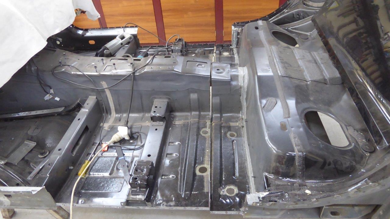
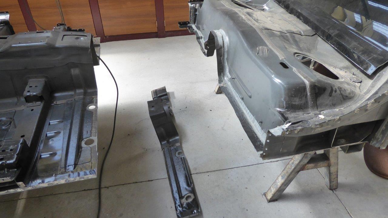
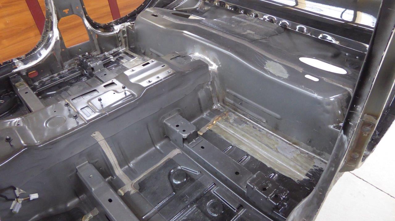
Sometimes I just need to see some progress instead of just spending a lot of time working through different options for the build. So one thing I did was address the moving back of the transmission mounts. The stock position is pictured on the right spot welded to the bottom the floor pan transmission tunnel junction. On the left I have mocked up the other mount after moving it back 140mm-5.5". This is how much I determined earlier I could move the engine closer to the firewall.
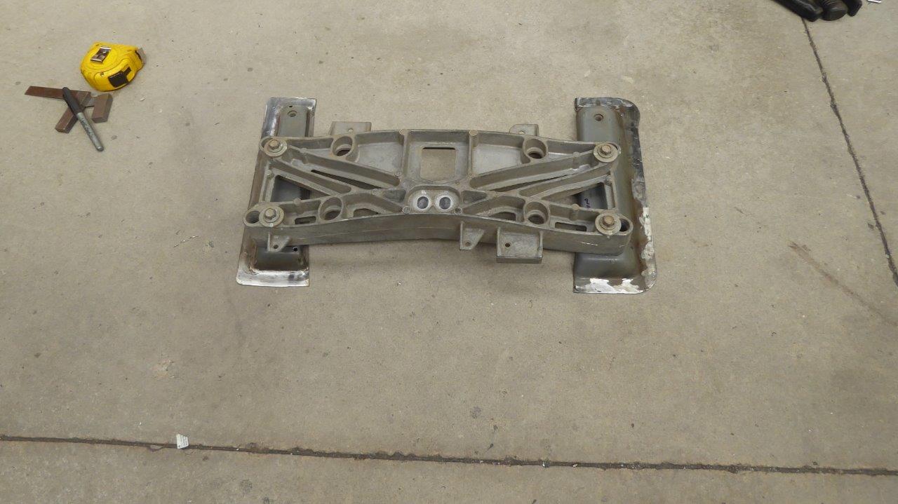
I cut the vertical parts of the mounts off and bolted it to the cast alloy transmission mount. It is actually made for either the 4 or 5 speed transmission options. The models of the transmission is cast into the piece with an arrow pointing which way to the front. You just turned it around and used the other set of bolt holes between the two models.
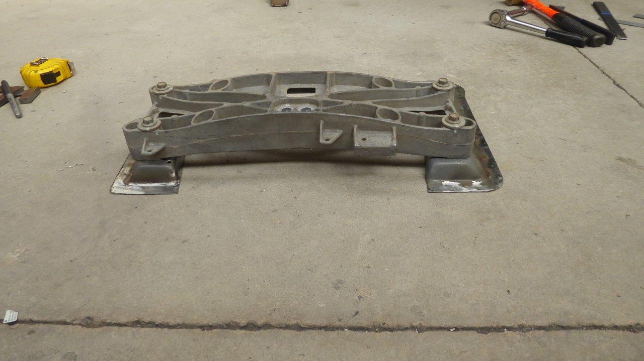
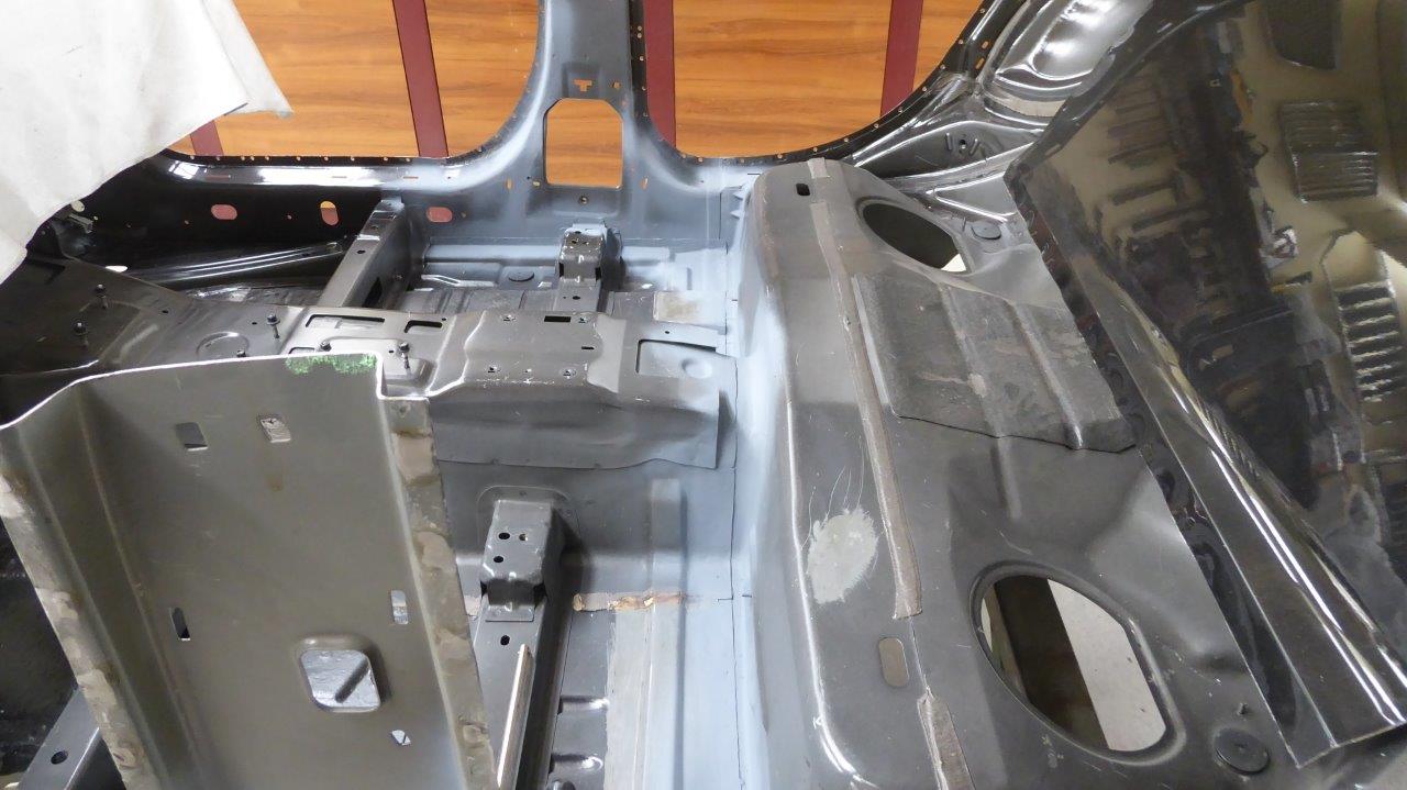
With the vertical flanges cut off I was able to slide the mount back on the narrowing tunnel the distance needed. Also making sure that I had it positioned exactly the right distance left to right as well.

A bit hard to see in this view, but made up some folded angle pieces that were curved to suit the tunnel shape so it was still supported on the sides of the tunnel and the floor as before. You can see by how much the flanges are now further away from the dropped section.
Notice here how much further away the dropped section is now from the tunnel edge. The vertical flange used to go straight down the side of it.
I used all the drilled out spot weld holes to plug weld the mounts back in, plus added extra for the area towards the rear. This is now ready for when I later start building the engine mounts after the Willys frame is in place.