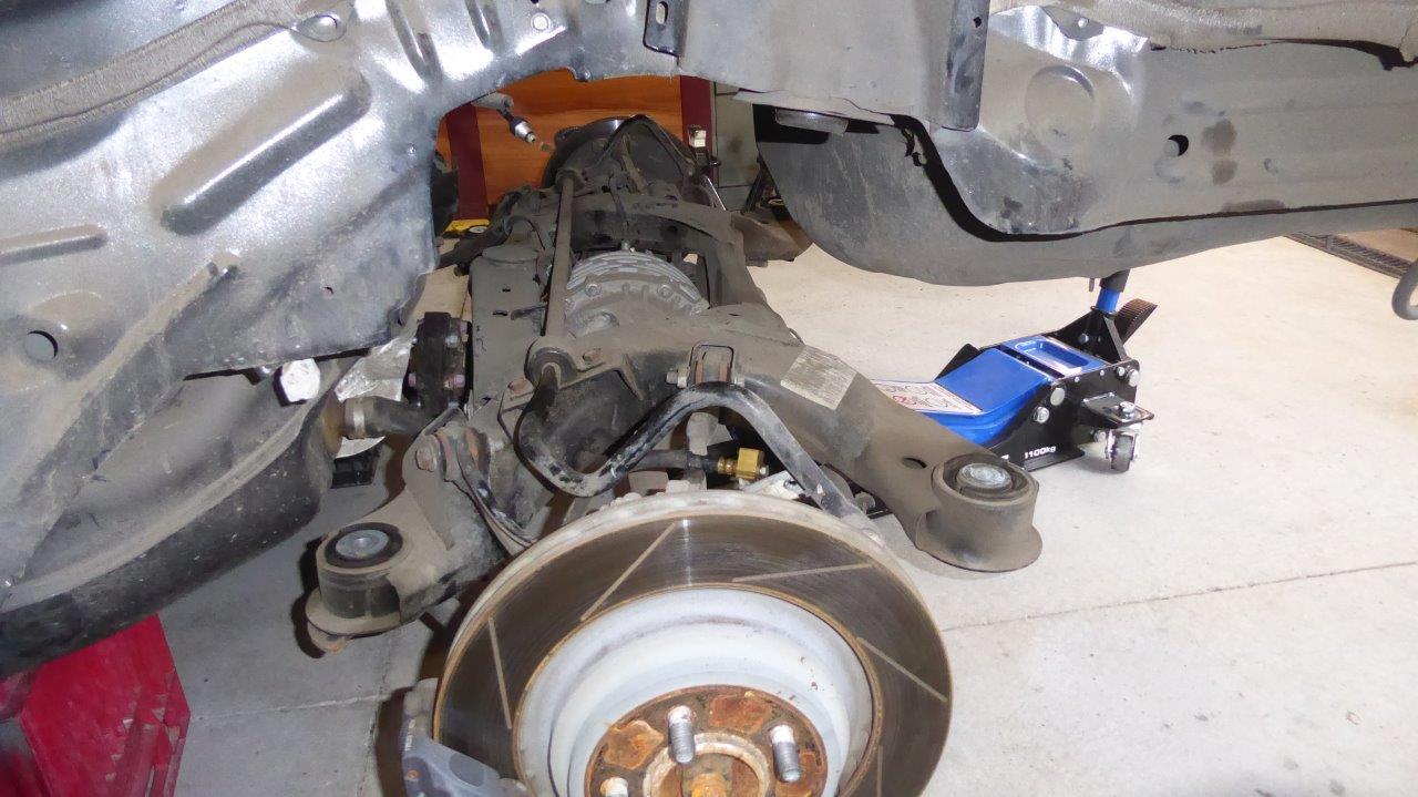

With the exhaust and driveshaft out, the brake lines and ABS already disconnected, the rear suspension cradle could be dropped. Just 4 bolts holds it in place and is fully contained except for the upper coil and shock mounts.
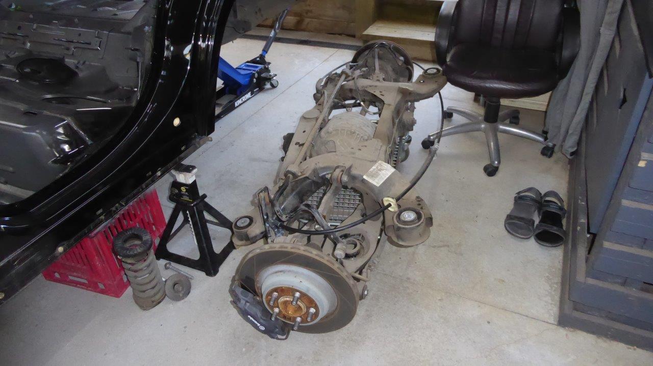
Rolling it out on the base of an old shopping trolley. Works really well and made a few of them up for the truck build.
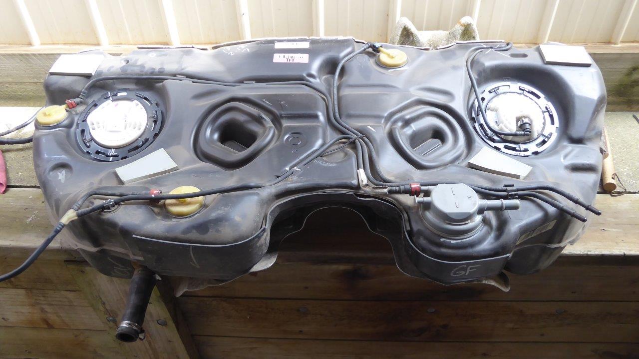
I did some research on how the fuel system works on the stock tank as I saw only an electrical connection on one side, but the fuel supply to the engine on the other, with no lines externally connecting the two! This is what is called a saddle tank due to the hump in the middle for the driveshaft and exhaust to run through leaving only a little space between them. This is just an example of why you have to plan ahead to use as much as possible from the late model donor if you use the electrical system. It's really is a case of use everything, or nothing at all! Below is a response from a Dodge/Chrysler engineer on Justanswer, when someone just asked what the ohms range was for the fuel level sender as was using this tank in an older vehicle and gauge cluster!
"The Fuel Level Sensor information is a bus message sent to the Powertrain Control Module (PCM) from the Body Control Module (BCM). On the primary side of the saddle tank is the Electric Fuel Pump Module that feeds the engine and the Primary Fuel Level Sensor. On the secondary side of the saddle tank is a venturi jet pump and the Secondary Fuel Level Sensor. The jet pump is connected to the Electric Fuel Pump Module on the primary side by way of a siphon tube. For each sensor, a high fuel level or volume will result in a low voltage reading and a low fuel level or volume will result in a high voltage reading (I.E. approximately 0.5 - 0.7 volts at the full position and 4.3 - 4.5 volts at the empty position) when operating properly. The PCM uses the average from both sides to determine the total fuel volume. The secondary tank Fuel Level Sensor will be at an empty position before the primary tank Fuel Level Sensor will begin to decrease due to the siphon tube flow rate always exceeding the engines fuel consumption rate. Using this assumption, the PCM performs a diagnostic to check the rationality of both Fuel Level Sensors, as well as the operation of the jet pump and siphon tube as follows; When the total fuel volume is greater than 50% the primary tank should remain at the full position. As fuel is consumed, or sloshes over to the secondary tank while driving, the jet pump and siphon tube will replenish the primary tank to the full position and the secondary fuel level should decrease. When the total fuel volume is less than 50%, the secondary tank should be at empty and the primary fuel volume should start to decrease as fuel is consumed by the engine. If either scenario fails to happen the PCM will determine that one of the Fuel Level Sensors is stuck in range, or that the jet pump or siphon tube is faulty not allowing fuel to transfer from the secondary side to the primary side of the Fuel Tank. The rationality diagnostic for the primary side of the tank will not become enabled until the secondary side level is near empty. The rationality diagnostic for the secondary side of the tank is based on the average fuel volume in the tank. It is enabled when there is enough total fuel to fill the primary tank plus enough fuel to check the rationality of the Secondary Fuel Level Sensor when a calibrated amount of fuel is consumed. Since the amount of fuel consumed from trip to trip varies based on customer drive cycles, this monitor can accumulate fuel consumption over multiple drive cycles. The monitor will run until enough fuel has been consumed to make a decision. Once a decision is made, a new test will start."
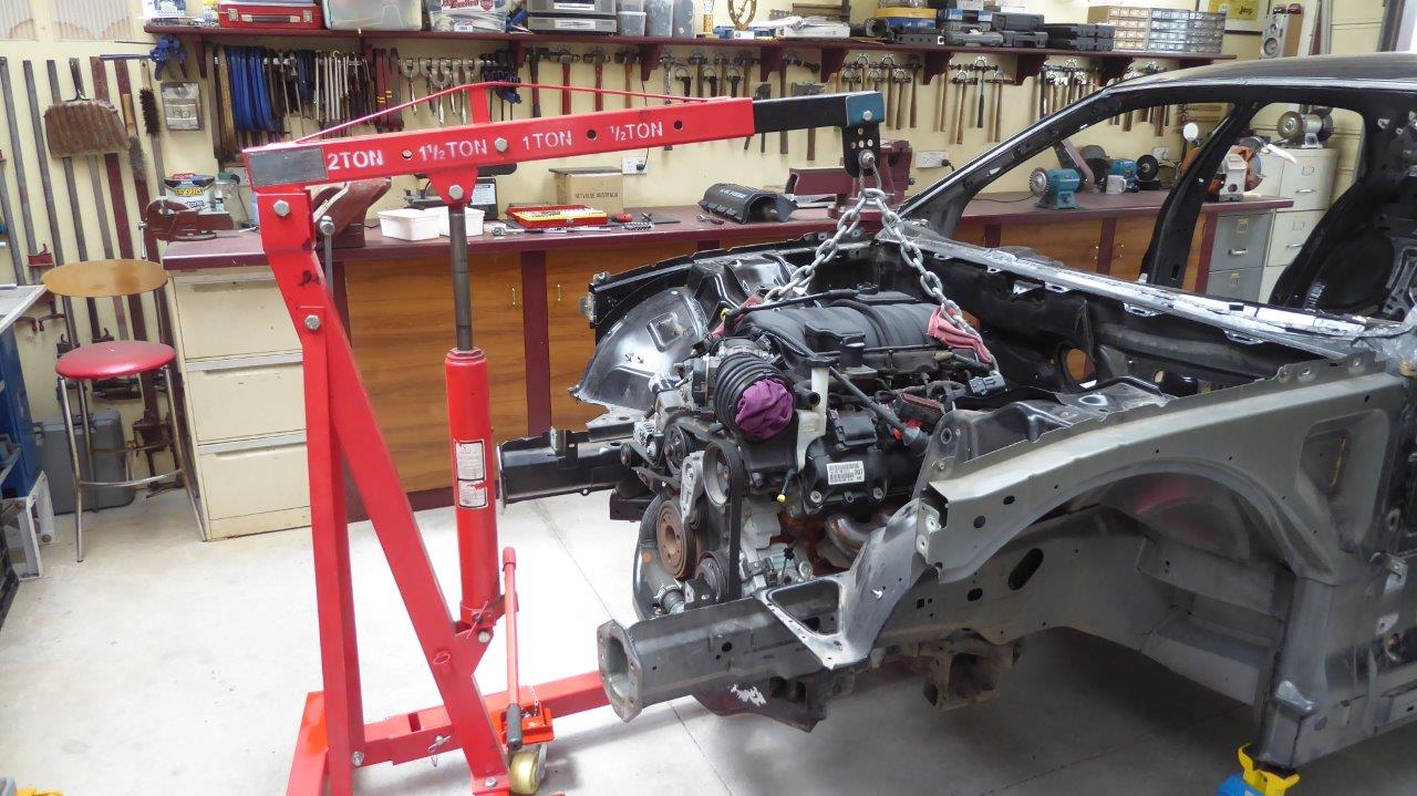
All that is left to remove is the engine and transmission. Only 4 bolts hold the engine cradle in place that also has the lower control arms and steering rack mounts etc too. Another 4 bolts retains the transmission cross member. I have the hoist crane attached to a bell housing bolt at the rear and a unused boss for the alternator at the front. There is also a trolley jack under the transmission mount to keep it level.

I just lowered the jack a bit and then the hoist, back and forth until I could easily remove the engine cradle from the engine mounts and get it out of the way.
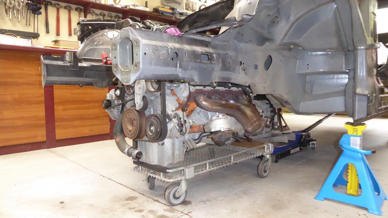
Pressing another shopping trolley into service to hold the engine and transmission. Front of the sump is on the padded cross bar and the front of the transmission pan is on a timber support wedged in the rear of the trolley base. The jack is not supporting it anymore.
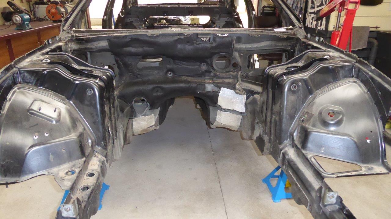
Nothing left at all bolted to the shell now. Everything now will have to be removed via cutting or drilling spot welds to get it ready for use in the Willys.
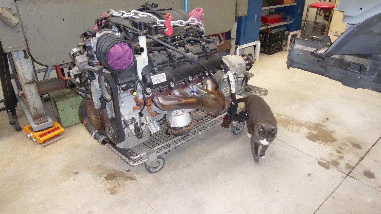
The engine and transmission wheeled out easily. They must really over engineer these shopping trolleys! Last time I had the transfer case hanging off the back as well.
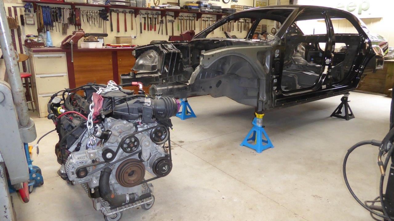
Free at last. Now fingers crossed that all the time spent on planning the cutting away of everything that I can't use is right, and the project all comes together back again in the end!
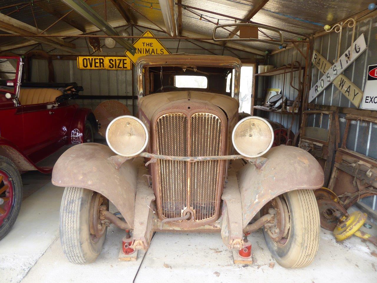
Just going over measurements of the two bodies now that is it easier with one of them completely stripped. It is clear that I need to do the wide body to be able to cover the track width of the SRT8 and also fit in the interior and the engine for that matter. Here is the stock front width which I have never liked as the grille is too tall and narrow for my liking.
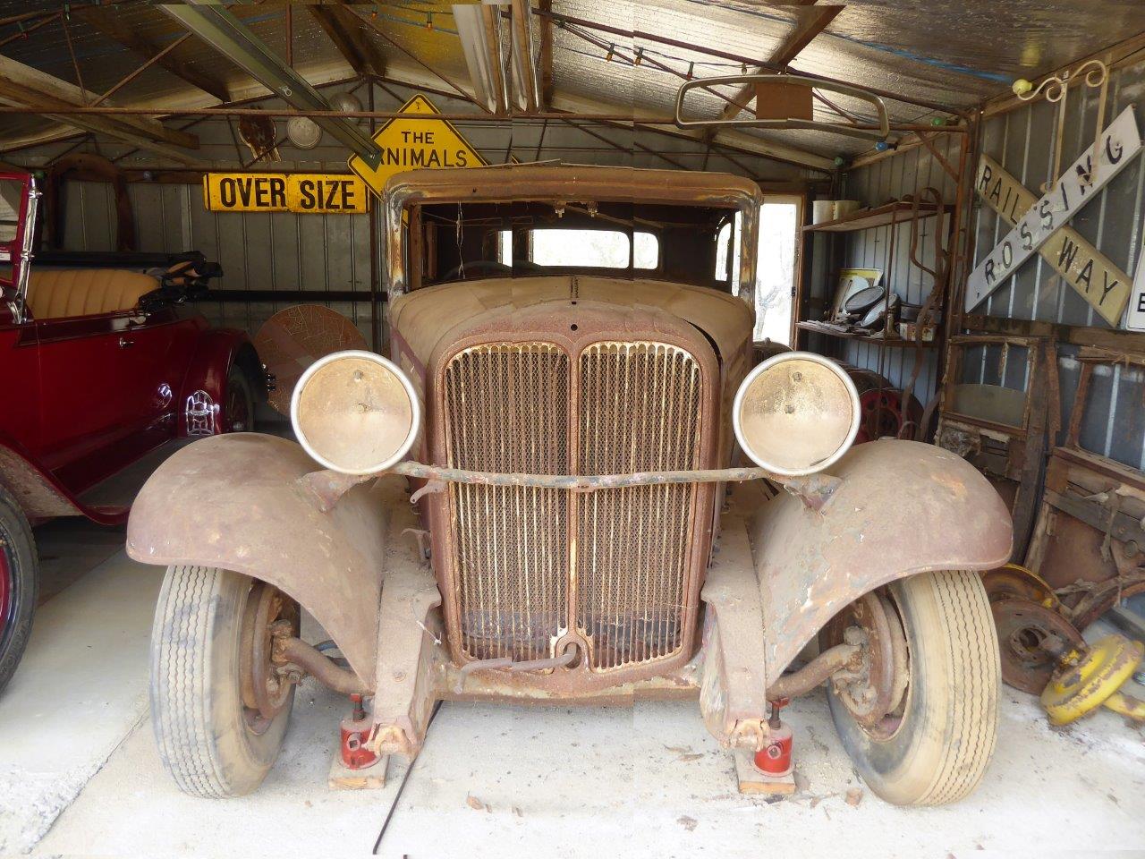
This is 5" wider with three slots or bars added each side which I thought I would have to do. But now it looks like one of the front guards had been hit side on reducing its width.
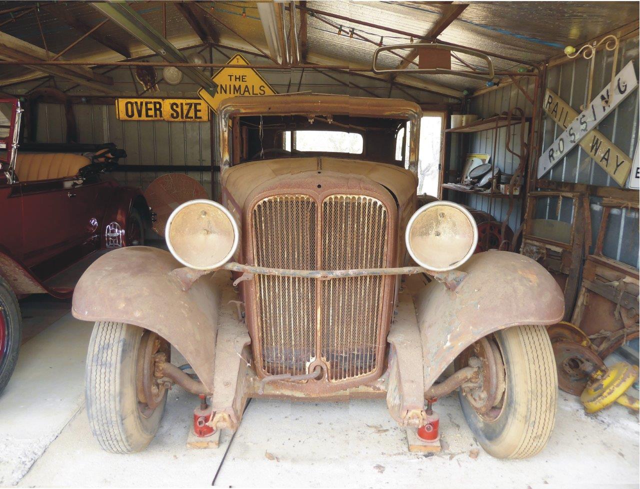
With some photo chopping this is adding two slots or grille bars each side to make it 3.5" wider. I do quite like these proportions as less 'Ford Edsel' looking and more like '32-'34 Ford grille proportions. I actually need 4", but this being so close it is easier to make up only 1/4" extra each side.
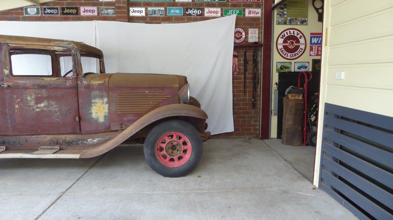
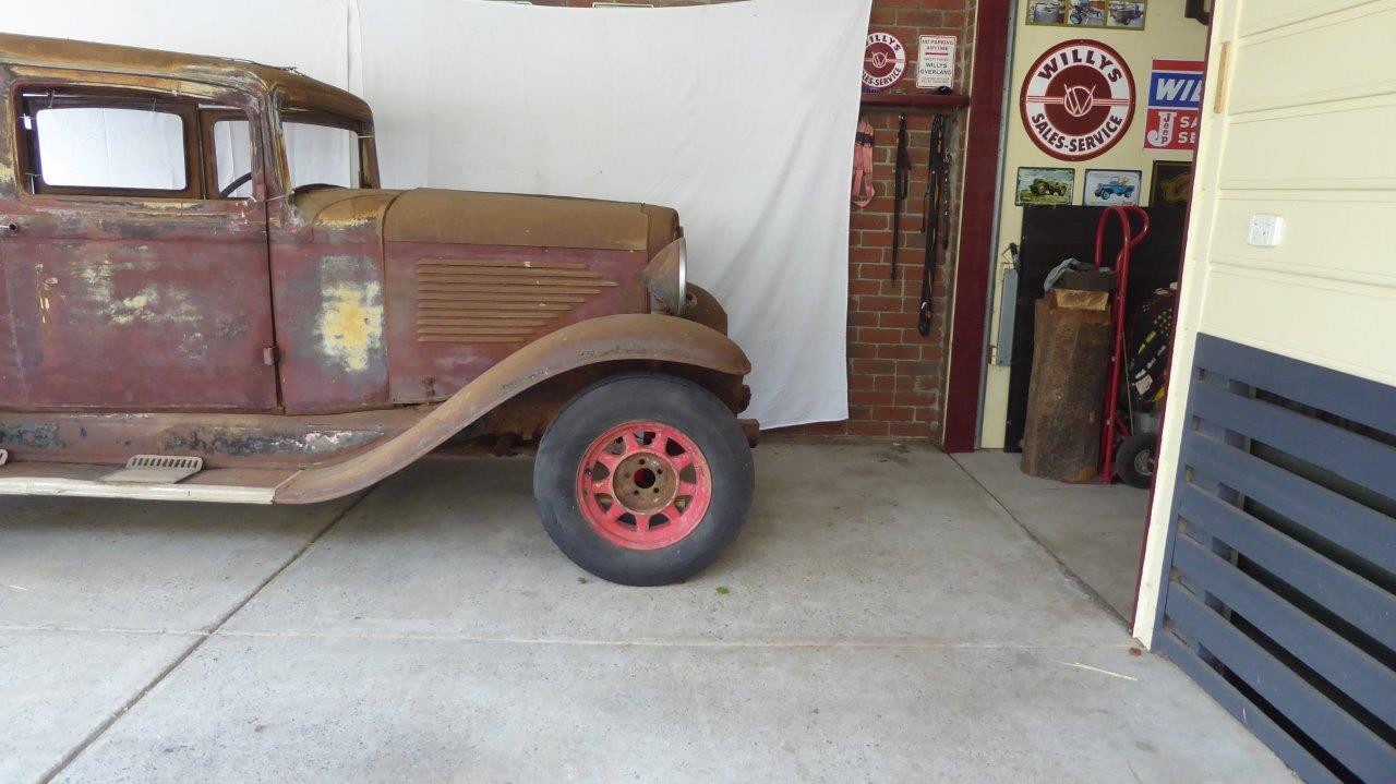
When the last owner bought this it was abandoned on a farm and the front axle assembly and springs had been taken to build a trailer for a water pump. So he used parts from his Willys 98 to sit it on, but gave me another set of springs which he said were the right ones for it. With the springs that are in it still it only measured 110" wheelbase and it sat like this.
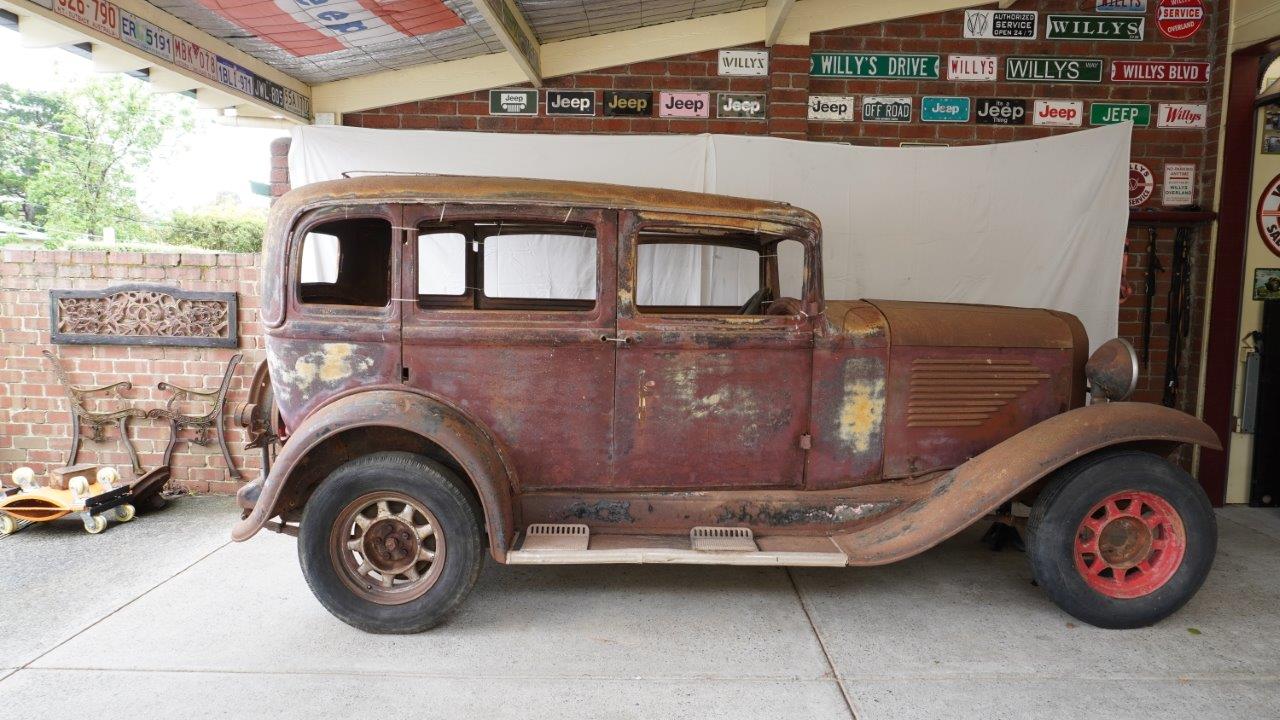
When I set the wheelbase back to factory specification of 113" like shown, it looks so much better!
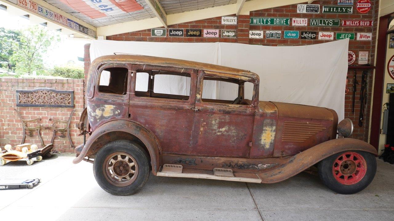
The rear springs are still in it and it is sitting with the running boards level in this shot. These Dunlop wheels are replacement 16" and have 28" tall tyres. Factory was 18" wire wheels, which I still have, and came with a 29"-30" tall tyre. Running board to ground clearance is 315mm or 12.5"
Now for some altitude adjustment! Dropped the front down and have the springs sitting on 100mm-4" blocks. Talk about hot rod rake!
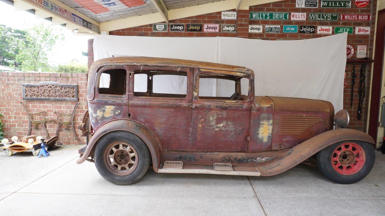
Now the rear is down as well. This drops the rear of the running board to 175mm-7" from the ground, and the front down to 150mm-6" off the ground. Keep in mind that the SRT8 donor only sat 115mm-4.5" off the ground with the stock suspension. So there is room to go lower and also still be above the legal 100mm-4" of ground clearance rule. The front guards will need to be remade with a higher arch above the centre of the tyre as there is only about 40mm-1.5" of room for up travel as it sits now.
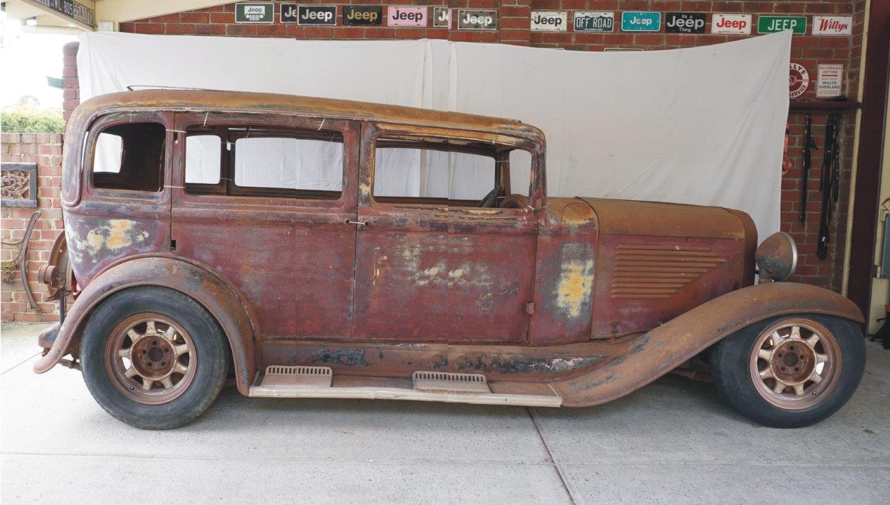
Excuse my chicken scratches using a 25 year old Corel Photo-Paint 9 program, but still gives us an idea of concept. I have never done a rendering in my life so it is as good as I can do. Now what this is showing is a 10" stretch between the firewall and the front of the rear wheel arch. This will allow the use of the SRT8 fuel tank to remain under the rear seat floor and still leave enough foot room for the rear seat passengers without having to move it back and make it much narrower. What I have done is add 5" to each door which also stretches the wheel base from 113" to 123". Only 75mm-3" longer than the SRT8 and 50mm-2" longer than the Willys 8-88 which was offered at the same time as this model Willys. Still means I have to shorten the SRT8 floor by 7.25", but leaves enough useable space inside. Overall the length of the Willys would end up an incredible 945mm-38" shorter than the SRT8 donor! The stretch gives an illusion of a roof chop without even loosing head room.
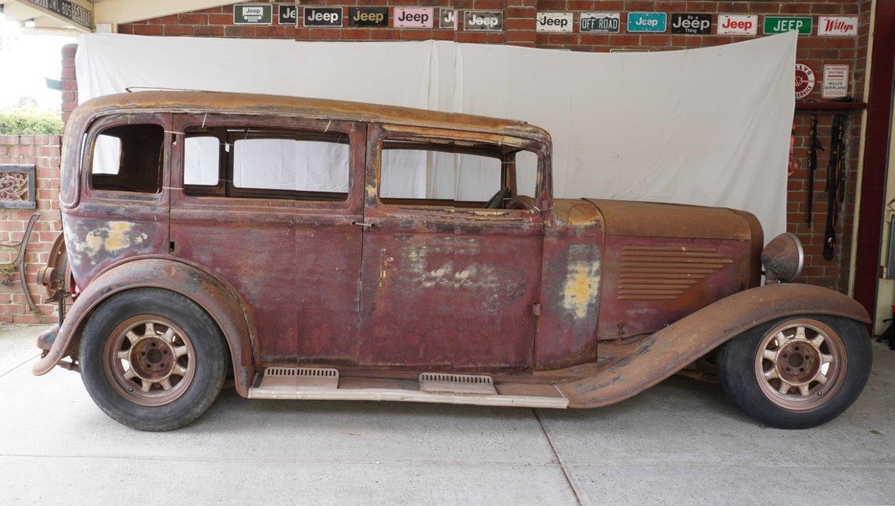
Here I have also extended the doors down near the running boards to see what that would look like. It makes the doors look less stretched and gives a different window to lower door proportion. One other thing I need to do is move the A pillar forward into the cowl area. Would leave the roof the same length but angle to A pillar forward only. A bit hard to do on such an old program though.
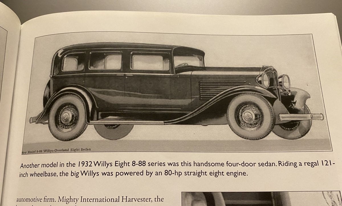
This shows what the very rare Willys 8-88 looked like. It had a straight 8 flat head making 80hp and had a 121" wheelbase. The bonnet is longer but notice also the C pillar is further forward on the rear wheel arch with a larger last window. My friend Chuck suggested the our model should be called a SRT8-88 then. The perfect combination of the SRT8 and 8-88 model names.
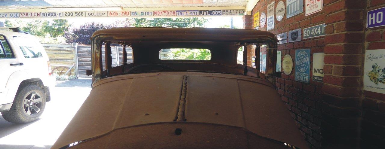
My biggest concern has been the difference in width between the A pillars between the SRT8 and the Willys. An incredible 460mm-18"! This is due to the massive taper in the body of the Willys with the width between the A pillars being 355mm-14" narrower than the C pillars. So I stretched the distance between the A pillars in the above photo making the windscreen 460mm-18" wider to see what it would look like. Better than I feared actually and gives it a very chopped look without loosing any height at all. The rear of the body will be made only 100mm-4" wider as planned, it just wont have the taper it does now and be the same width all the way down the body.
Video update showing the ideas of the build.