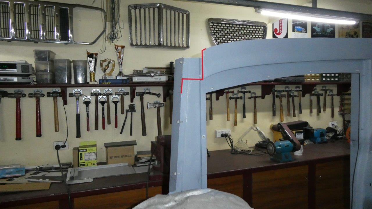
Starting the header panel, or upper windscreen support, connecting across the car for the first time with new steel work. This will be made in two pieces with the upper section having two folds and the lower just one before being welded together. The little return at the top serves two purposes as it flows into the top of the inner door support. One is that it adds stability to the vertical flange to keep it ridged, and the other is later the outer piece will sit on this and the two spot welded together.
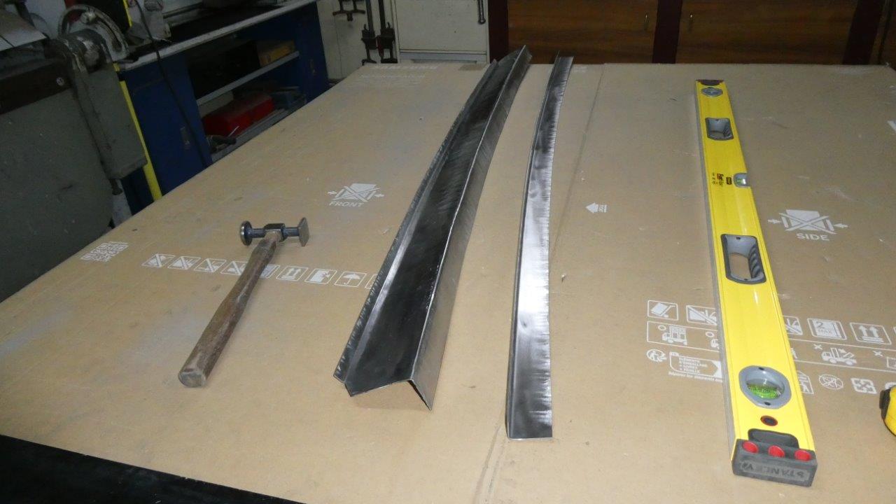
Now I was thinking that I was going have to spend a lot of time making a new template to match the stock curve of the factory stamped Willys windscreen opening. First wondered though if one of the other templates I had already custom made would be close. Well it turns out I had unwittingly made the exact matching curve when I ran the wire from my gate to the side of the house when building the side body profile! So used that profile to get the curve in the vertical plane for both pieces. It was just folded straight and then curved using the shrinker/stretchers. The top flange was then tipped last in the bead roller.
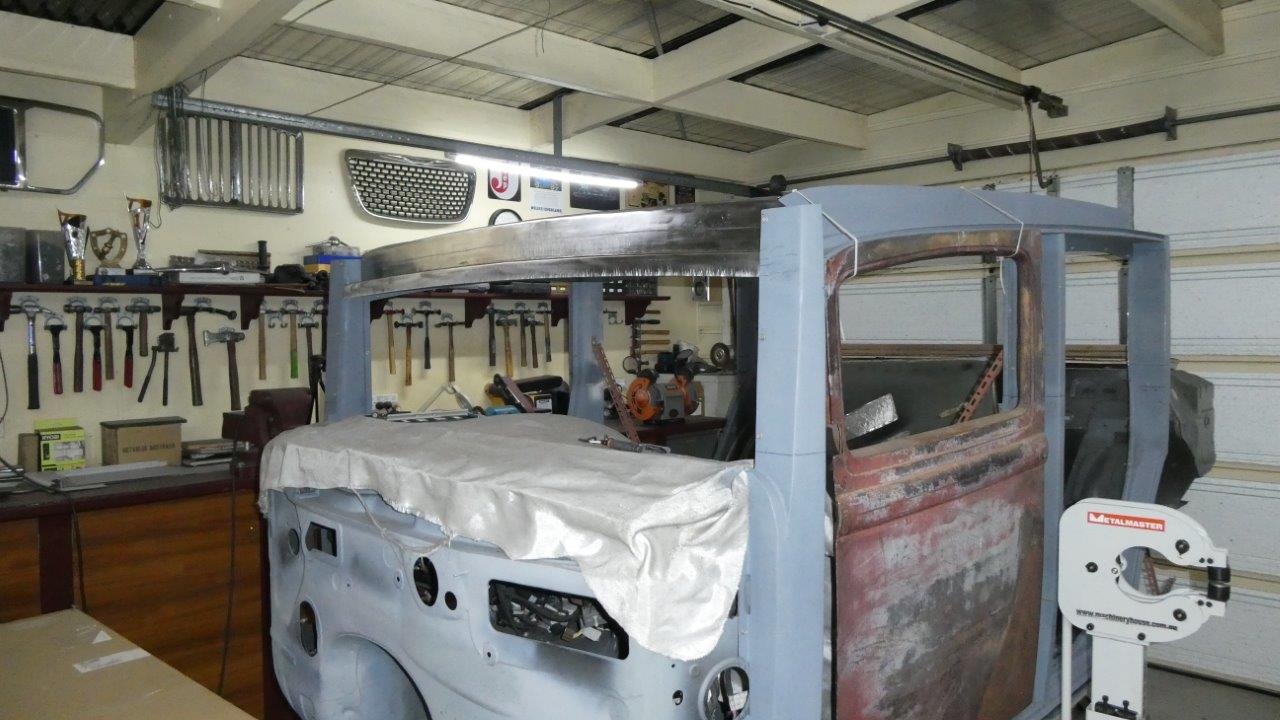
Both pieces were then TIG welded together and the weld ground, planished and sanded smooth. Starting to get a feel what the proportions on the windscreen is going to be too!
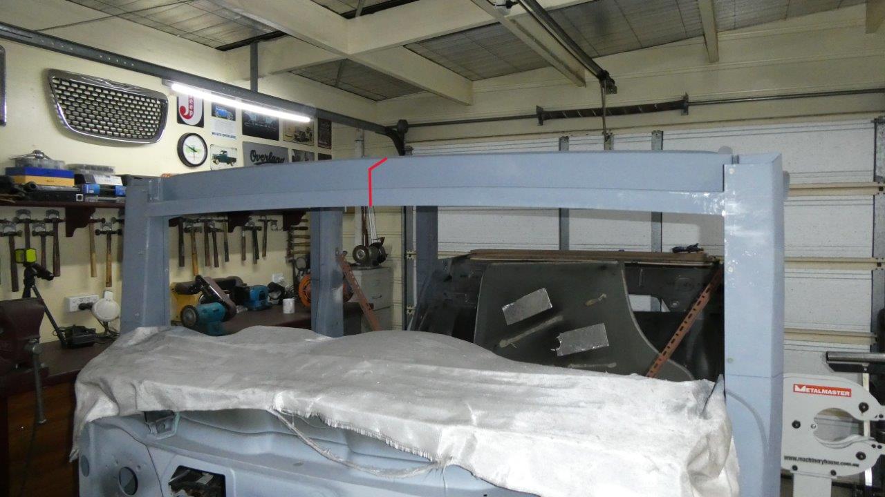
The next piece to be made boxes in the support starting at the bottom of the last piece, which is going to become the pinch weld the glass gasket sits on, it then extends up and then to the back of the flange on top of the other piece. All this sits under the roof skin and front panel from the Willys body. Inside this cavity later will be the wiper transmissions driven from the donor motor attached to a Lucas cable system located in the passenger under dash area. Most likely need four wipers to cover the the legally required amount of sweep area. That is worked out on covering 94% of the drivers primary focus area followed by 80% of his peripheral vision to be able to see his mirrors etc. 25mm-1" around the border of the glass is not included in the calculations. Passenger side must cover 99% is this measurement. Australian Design Rules (ADR) No.16.
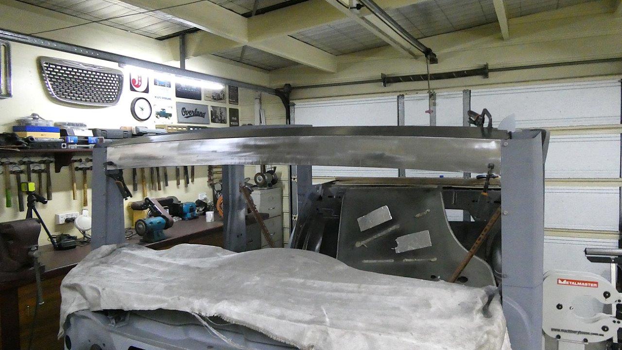
This piece was cut out with the curve shape and tipped in the bead roller as it had too much depth to try and do it with shrinking alone. Some perfecting afterwards was done with it though.
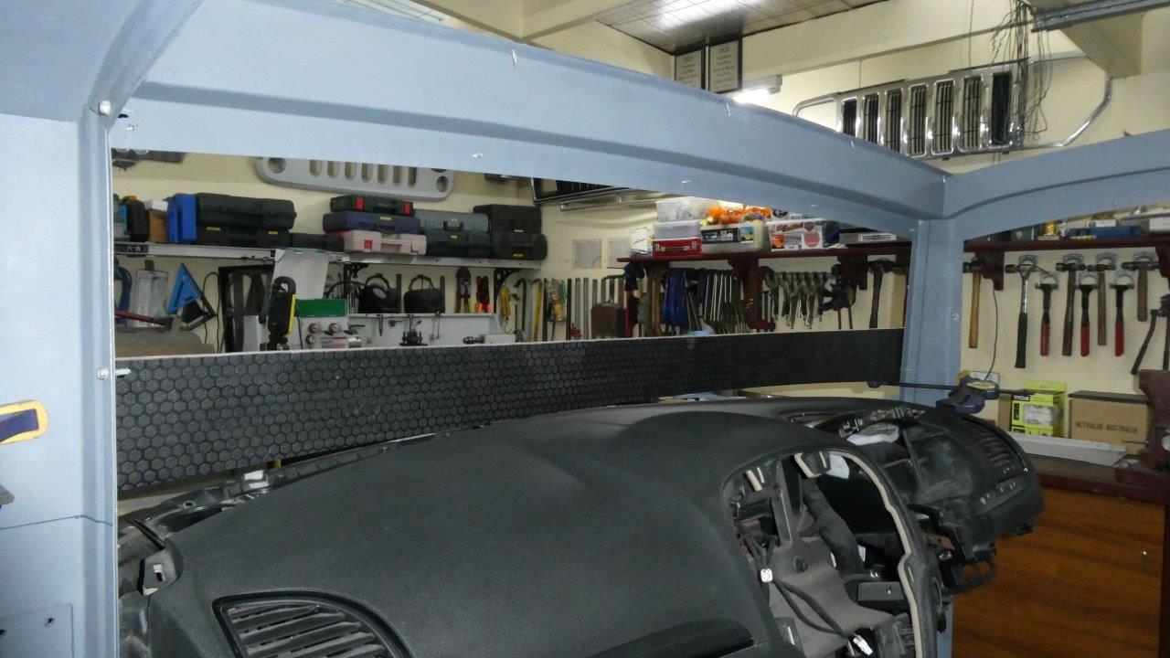
Here you can see the inside upper support fully welded in with the outer just tek screwed into place for now. Also notice the extra depth of the pinch weld area that is 40mm-1.5" high, which is more than needed for the glass gasket to sit on. I designed it this way so the bottom of the boxed section lined up with the door supports for a better header to windscreen transition, but also that I can cut this up to 26mm-1" higher later on should I have a need to start the glass area from higher up like the 33-34 Fords have. I also have the template in place so I can start working out where to start building the lower support from the bottom of its curve.
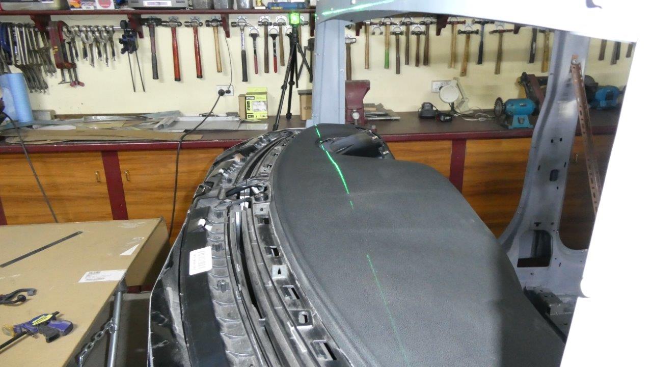
When I positioned the A pillars right in the beginning, I was already making sure everything would workout once I got to this place in the build. Any further back would have meant not leaving enough room for the instrument cowl to sit below the glass gasket. Also it would have made the front door shorter than the rear one which I don't like the look of. The laser line will only be a starting guide as it does not take into account the 3° angle of the front of the A pillar, so further trimming of the higher areas will be needed.
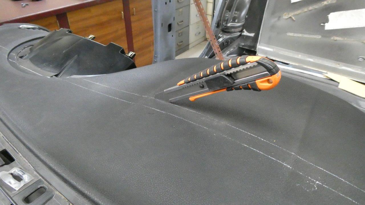
A second line was drawn behind the laser one for the amount the support width is back from the pinch weld/glass line. Made sure I fitted a brand new blade before cutting into the flawless dash top!
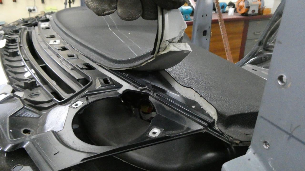
I just cut through to the hard plastic shell underneath until I know just what of that has to be cut into as well. I wanted to leave as much as possible of the plastic, but still have enough depth to the support for the required strength needed. The polyurethane foam under the vinyl layer was stuck down, but using a metal scraper I was able to free it while pulling up.
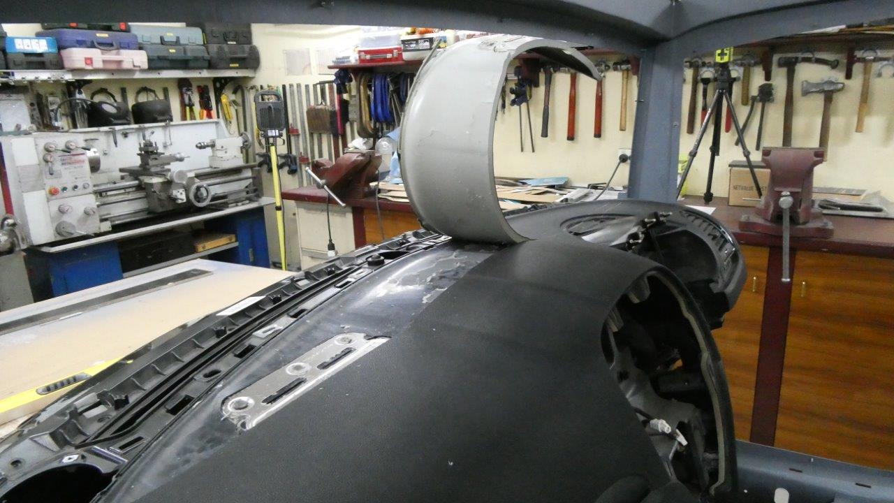
Certainly no turning back now! The metal section holds a bracket underneath that the passenger airbag bolts too. I thought I'd better remove the airbag before cutting any further down through the dash!
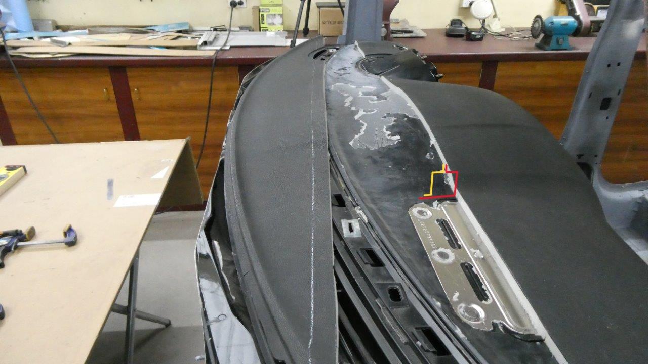
The red and the yellow outlines show the design of the lower support. It incorporates a top flange that lines up with the front of the A pillar pinch weld for the glass gasket to sit on. Also will have a pinch weld flange out the front to make it easier to spot weld the two halves together. The support only has to hold the weight of the glass as there is already a main support structure connecting the two A pillars together inside the dash that holds up the steering column etc as well. The cowl will also connect all the way along near the top of this support on the outside piece.
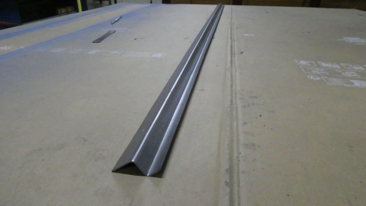
Starting with part of the back piece draw in red above. This is just the first half of it as the folds are too close together to make it in one piece unfortunately.
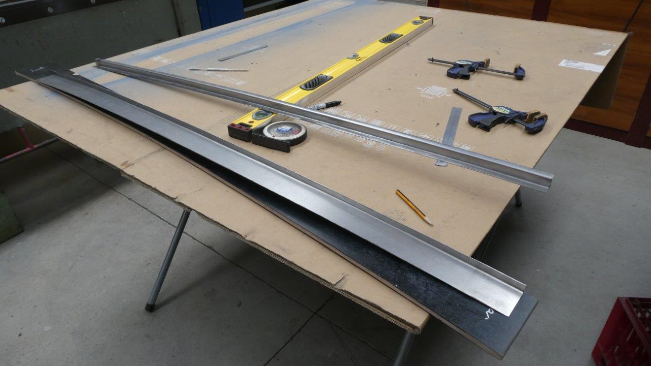
The top Z piece was curved by carefully balancing the amount it was stretched along the top flange while shrinking the bottom one. Must be done just right or otherwise the folds will no longer be 90° and it will start to twist and turn. The bottom half of the rear support is just an L shape and the short flange just needed stretching to match the template and the Z pieces bottom edge.
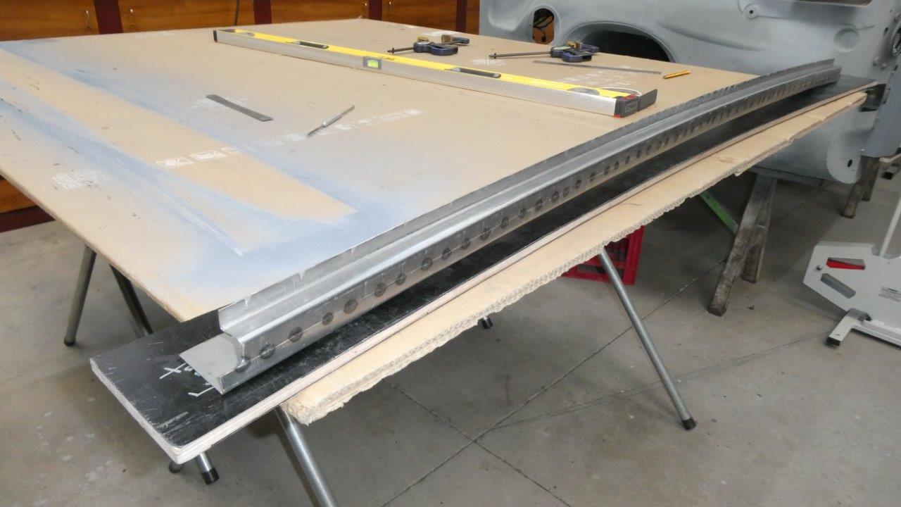
The two were tacked together and matched the template vertically and was dead flat horizontally. This is very important that it remains this way after welding as the glass follows the top flange. However, even though everything welded well and I carefully stretched the weld afterwards, it fought me for days! It would be perfectly flat but then have too much arch. Get the arch perfect and wouldn't be flat anymore. I was getting pretty worn out trying all my usual tricks to get it perfect.
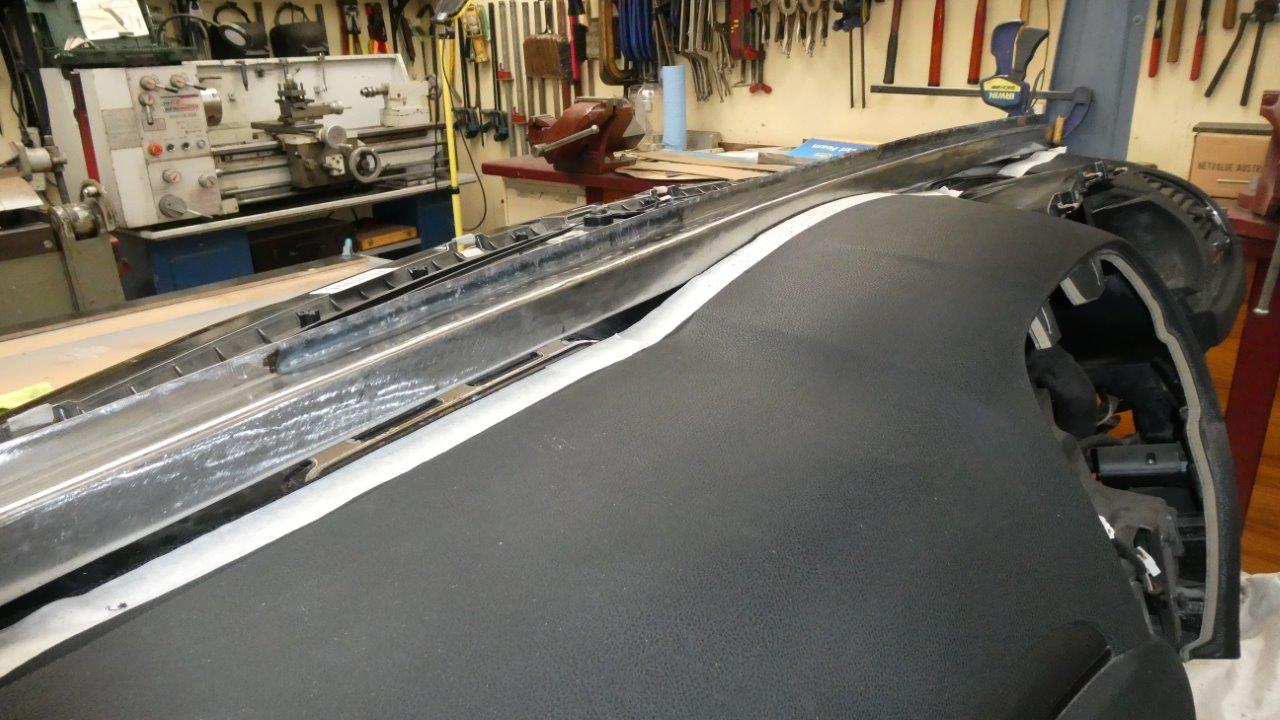
In the end I have the shape right but there are still a few imperfections left. I just had to move on from all the hammering and progress with getting it closer to the final position. With it clamped at the A pillar angle, I could sight down the face of the support and ran tape where trimming was needed. Just trim away where it was touching and then lower the support some more and repeat.
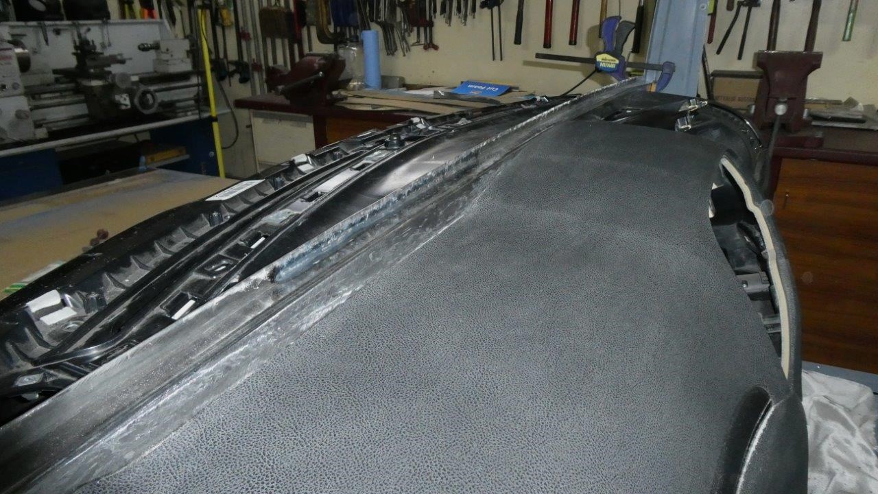
I had to cut right through the plastic shell of the dash cover over all the high spots. Finally got it down where the top flange, once the window gasket is added, will be level with the door window sills.
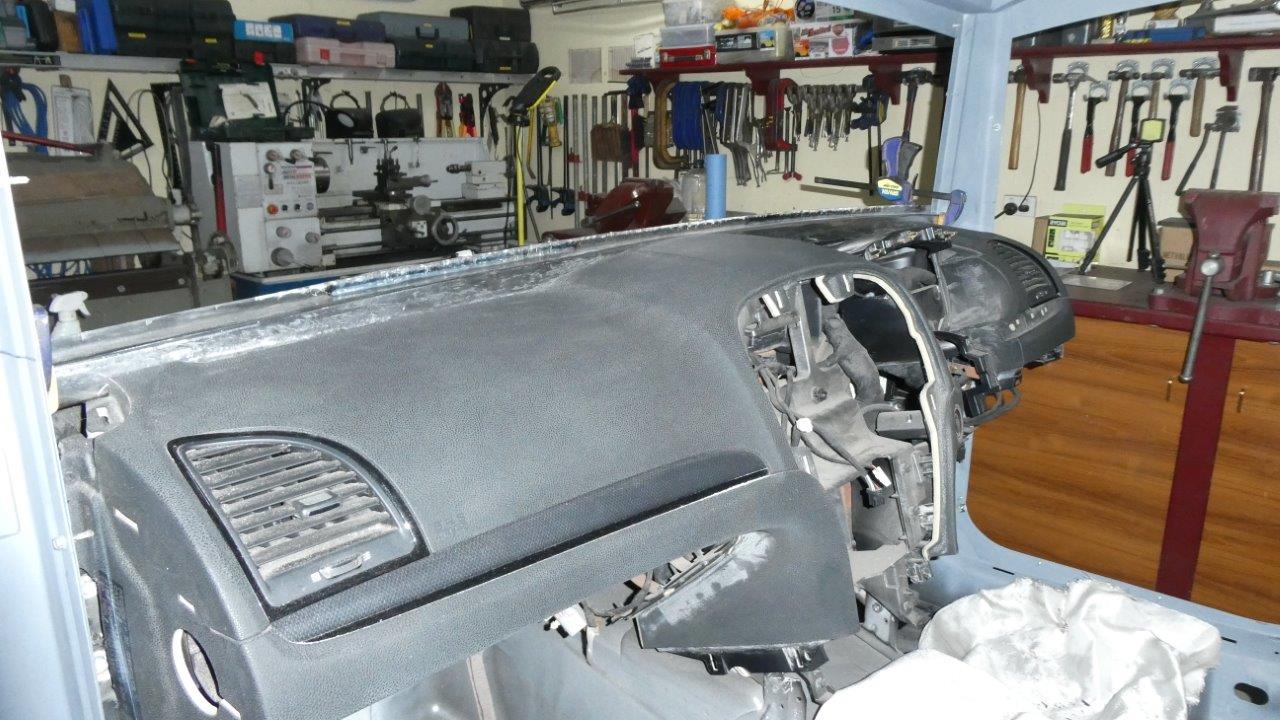
Notice also that the top of the support is now level with the top of the highest point of the dash cover too at the same time. I already worked this out when setting out the height of the door window sills a year ago and why they are higher than what the donor had them at.
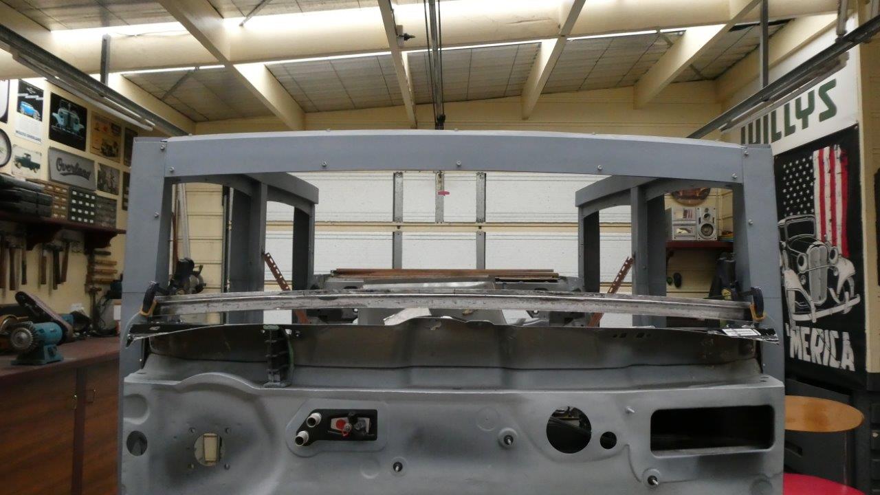
So now you can see what the true proportions are going to be like for height and width of the windscreen/windshield. It is actually stock height but 448mm-17.6" wider! Remember this looks way to blocky right now and all the step and rounding of the bodies skin isn't in place to soften it. These are no thicker than stock, just look that way.
Unfortunately my body has had the old RSI injuries come back in my elbows and shoulders that only happened right near the end of the truck build. They are back after only a just over a year in this time. Guess now being in my 60's means it has come sooner. The joints are very painful and inflamed so have stopped the fabrication work for a while. But seems like now is a good time to start rendering what these proportions are going to look like from the front view and if they are acceptable or not. Also have started learning Fusion 3D and bought a printer last week so I can design and print the defrost ducts. Been looking at changing the way I have been fabricating to reduce the amount of planishing after welding too. More on that soon!