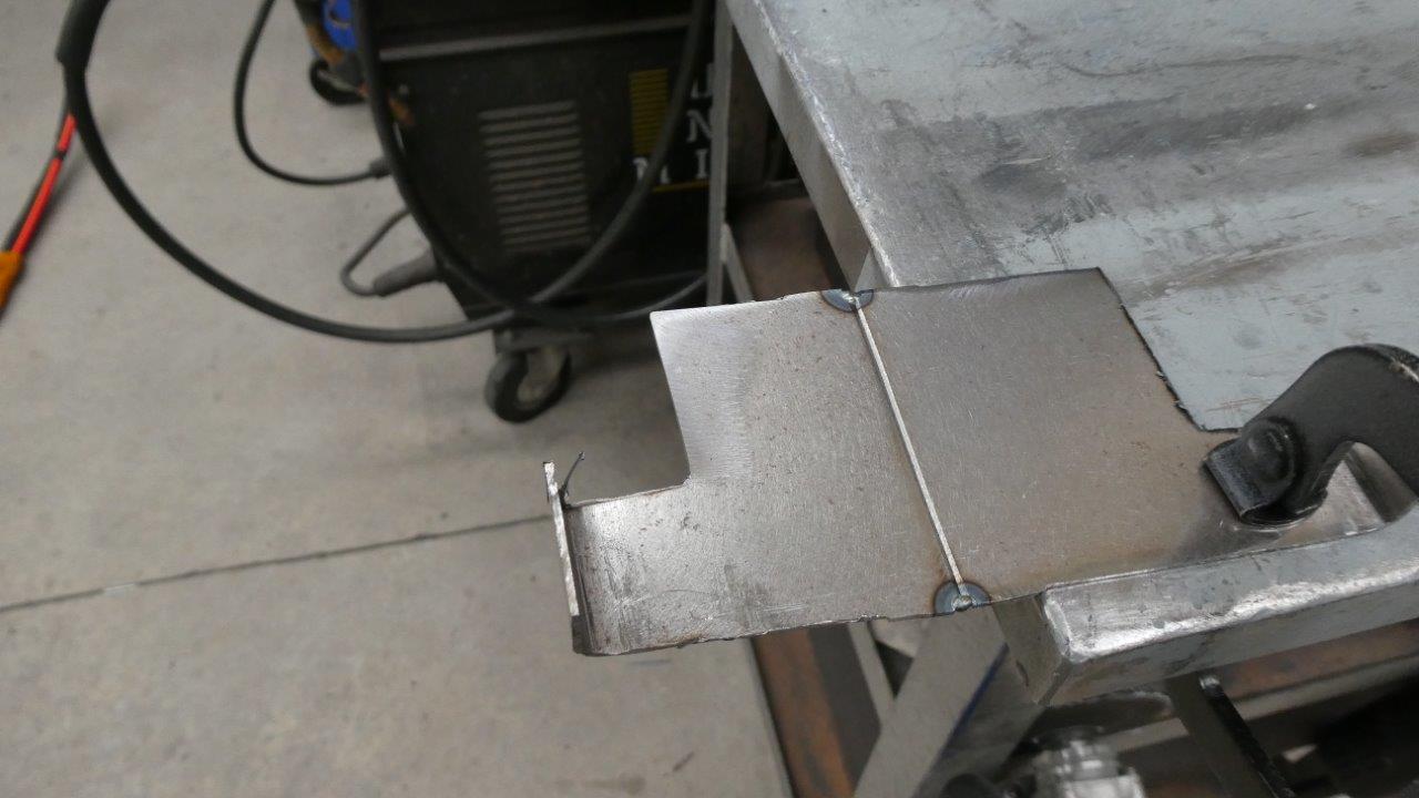
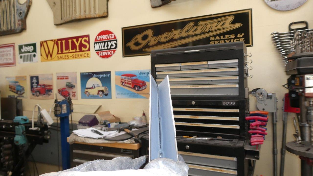
Now onto some sheet metal. I noticed a lot of comments about how hard it is to keep on track when welding no gap butt welds. Some even putting a fence alongside the join to keep from wandering. Part of it is the sheer speed the pass is happening at compared to MIG or TIG, but also being able to see the join before it gets to the laser, as it is under the nozzle. So what I found is a very quick 45° pass with a flap disc each side to make a bevel to about half the sheet metal thickness. Something I normally only do on plate steel, but works well here too. Normally this would cause a big risk of burn through and blowouts, but not with a laser. This is some scrap 1.2-18ga. cold rolled mild steel which is what all the inner structure is made from. I have tacked the ends and the steel is flat. You cannot tack or weld directly on the bench as the laser will weld the piece to it. I just use a strong magnet to hold it as you have no trouble with pulling the arc away like with a TIG if too close.
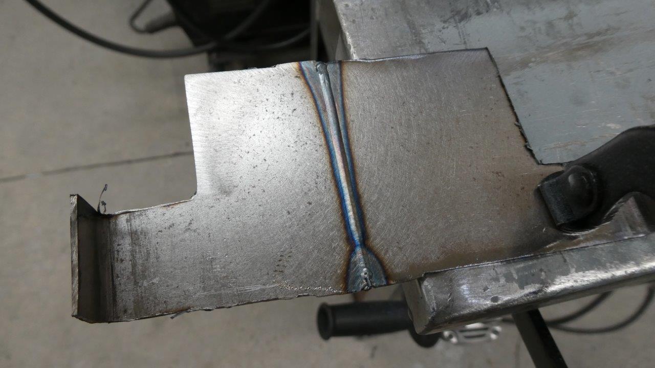
This was with wire speed and power % settings for 1.0mm-20ga. Didn't penetrate all the way through as you would expect with this being thicker. So I adjusted the settings and have video of the welding taking place.
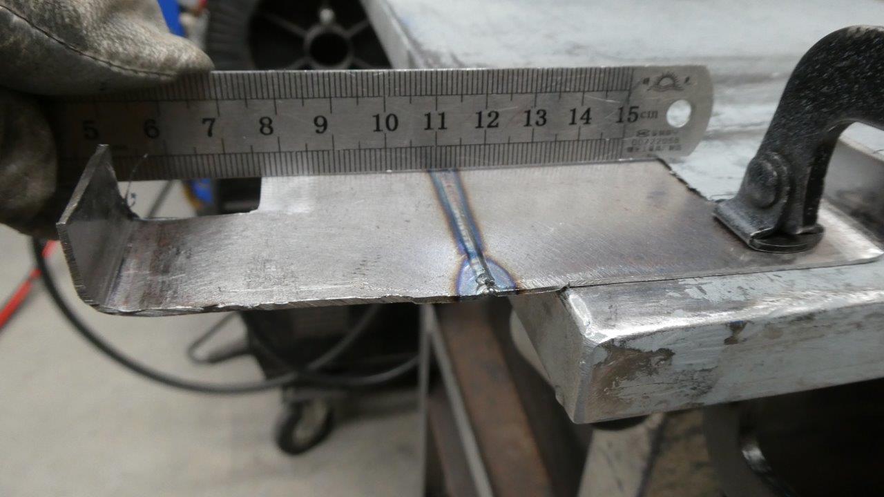
Look at the lack of distortion and I think the slight gap is mainly from one end of the ruler sitting up on the swarf! Didn't notice that until I looked at the picture later.
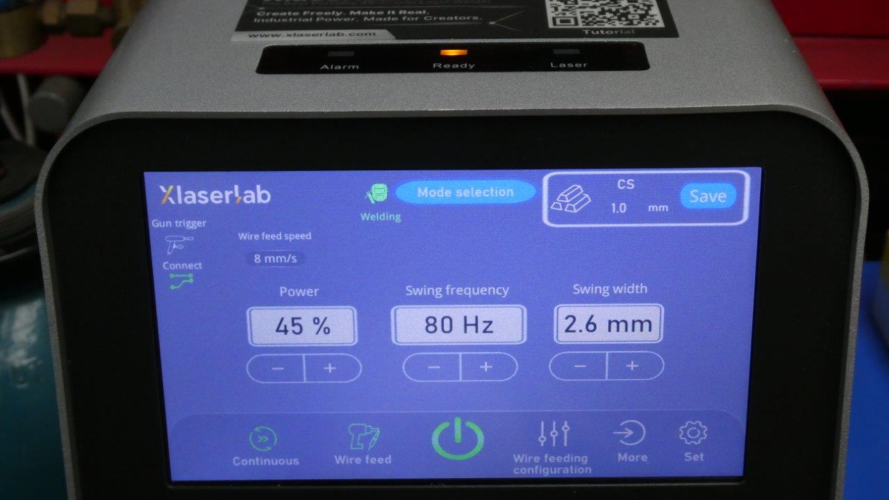
These are the settings I used to get full penetration on the thicker 1.2mm-18ga. Started with the 1.0mm CS and changed the swing width to 2.6mm from 2.0mm to flatten the weld and I slowed the wire feed rate down from 10mm/s to 8mm/s. Reducing the speed of the wire coming out slows your travel speed over the join and means the laser is putting more heat for every millimetre of travel. This gives it time to melt all the way through the sheet. Could also have increased the laser power too for the same result, but I wanted the slower travel speed while I still get used to it. The standard settings only go up in 1.0mm increments and you can save you preferred settings by pushing the blue saved button in the upper corner. Just be mindful though that you loose the factory setting once you do that for that thickness, so I have taken a screen shot of the factory settings before saving new ones.
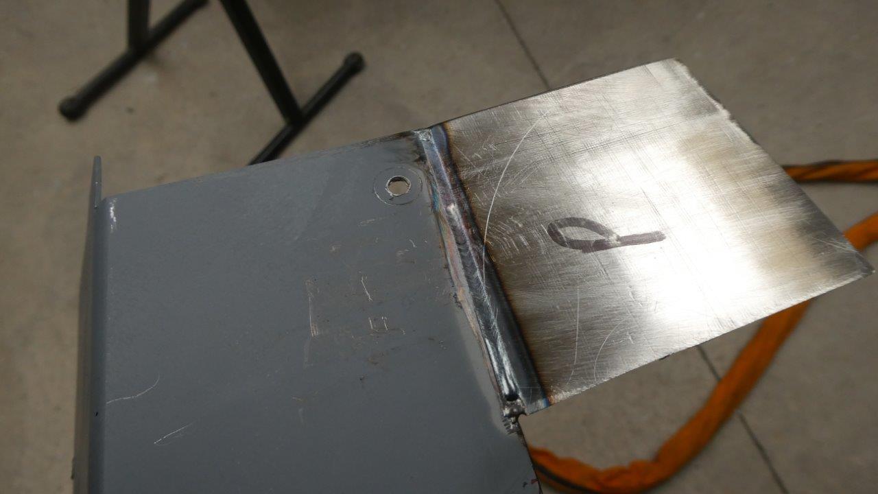
This is the outer header panel above the windscreen and I am adding the rounded upper corners. I started with a piece scrap and will cut the inner curve after it is welded. Did the 45° bevel and have the new settings dialed in. Notice the the weld has flattened and doesn't even need any grinding for most of it!
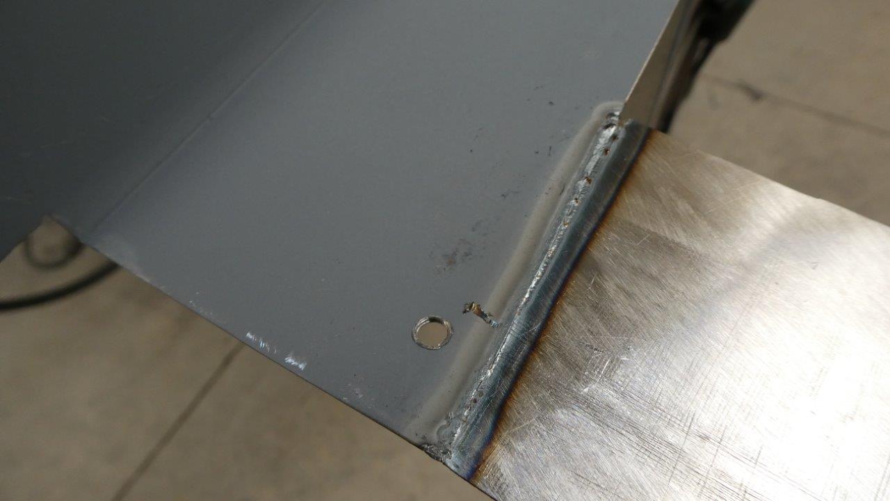
Penetration on the backside is just perfect.
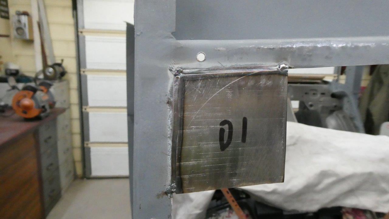
Repeated the same process for the top of the A pillar to inner header panel junction as well. I was a little heavy handed on sanding the bevel on the top seam and you can see the weld has sank in a little and come through the back side more there too. Will make sure in the future that I bevel only halfway like the rest of the joins with these settings. The build up at the ends and corner is from tacking where I float the laser in the one spot but don't travel at all. Way easier than using a TIG, that is for sure.
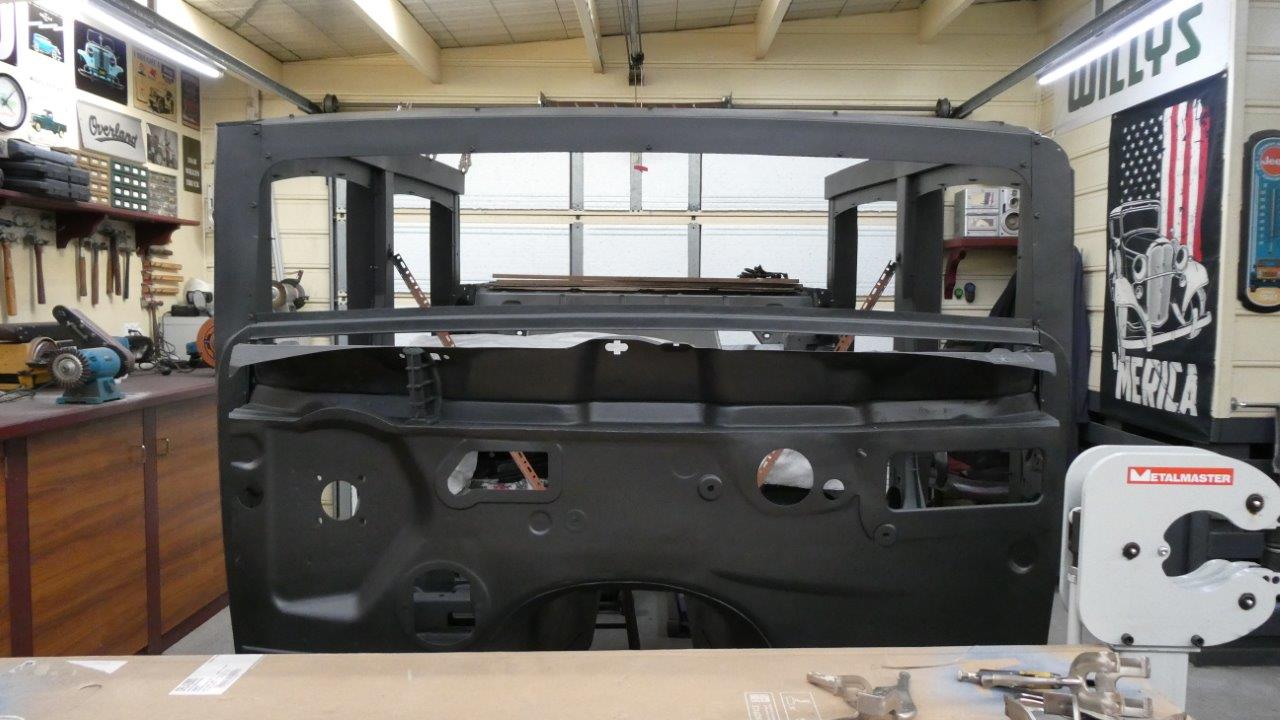
The top corners and now rounded and one outer corner as well. The lower windscreen support was also fully welded in and everything has been hit with a black zinc top coat to protect the metal.
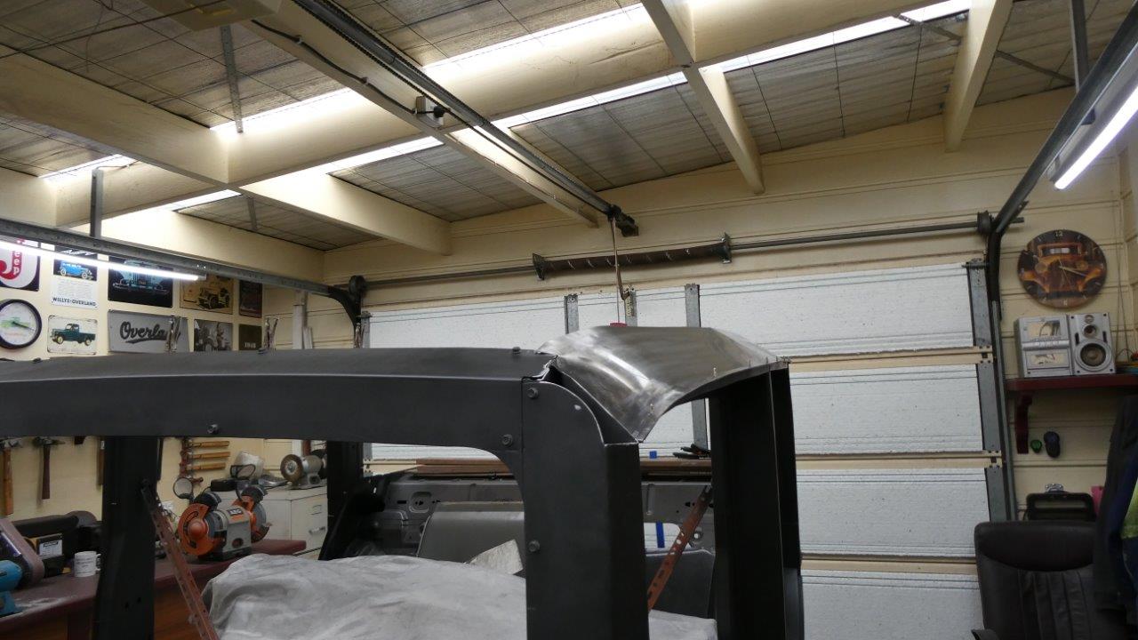
The next pieces made connects the top of the inner upper door structure to the gutter that runs along above the doors. I just laid some cardboard between the A and B pillars, and then another between the B and C. Then traced along the edges and added some extra for the gutter flange. Between the B and C pillars it required no shaping other than bending a gradual curve over my knee and a little stretching along the gutter edge. These panels will never be seen and are just there to stiffen the whole upper structure, so was not worried about putting shape in them. The front where it connects to the A pillar needed more work to dip down following the gutter line and connecting the the back of the A pillar however.
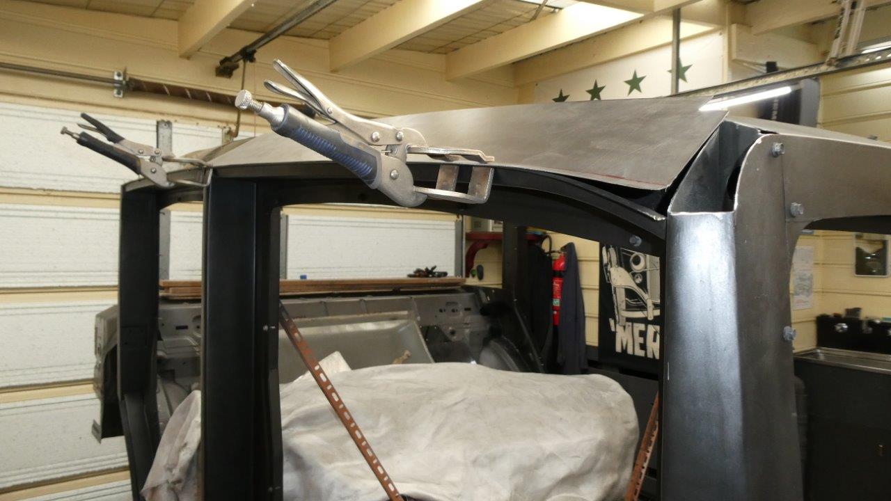
On this side you can see why more shape is needed to curve downwards while still following the outside edge of the gutter.
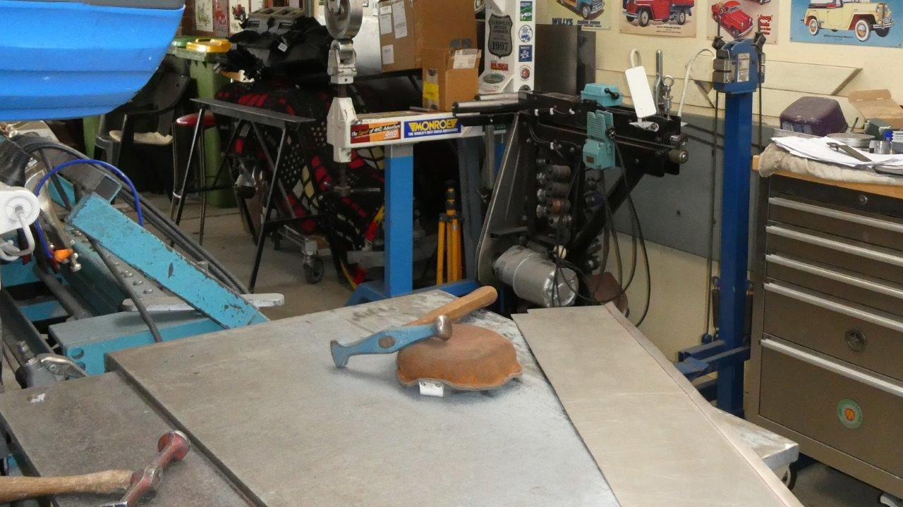
I hammered the curve in over my little hand beater bag as it saved lifting one of my big ones out of the bottom draw. Unfortunately didn't get any shots of what it looked like after hammering and then passing it through the English Wheel. That was because I actually shot it on video for anyone that might be interested in it.
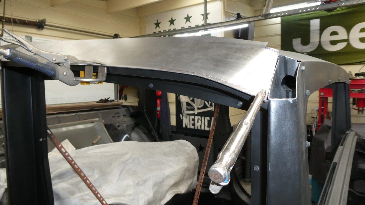
The panel now has the shape required to fit nicely except for a little more bending at the very top where it meets the header panel.
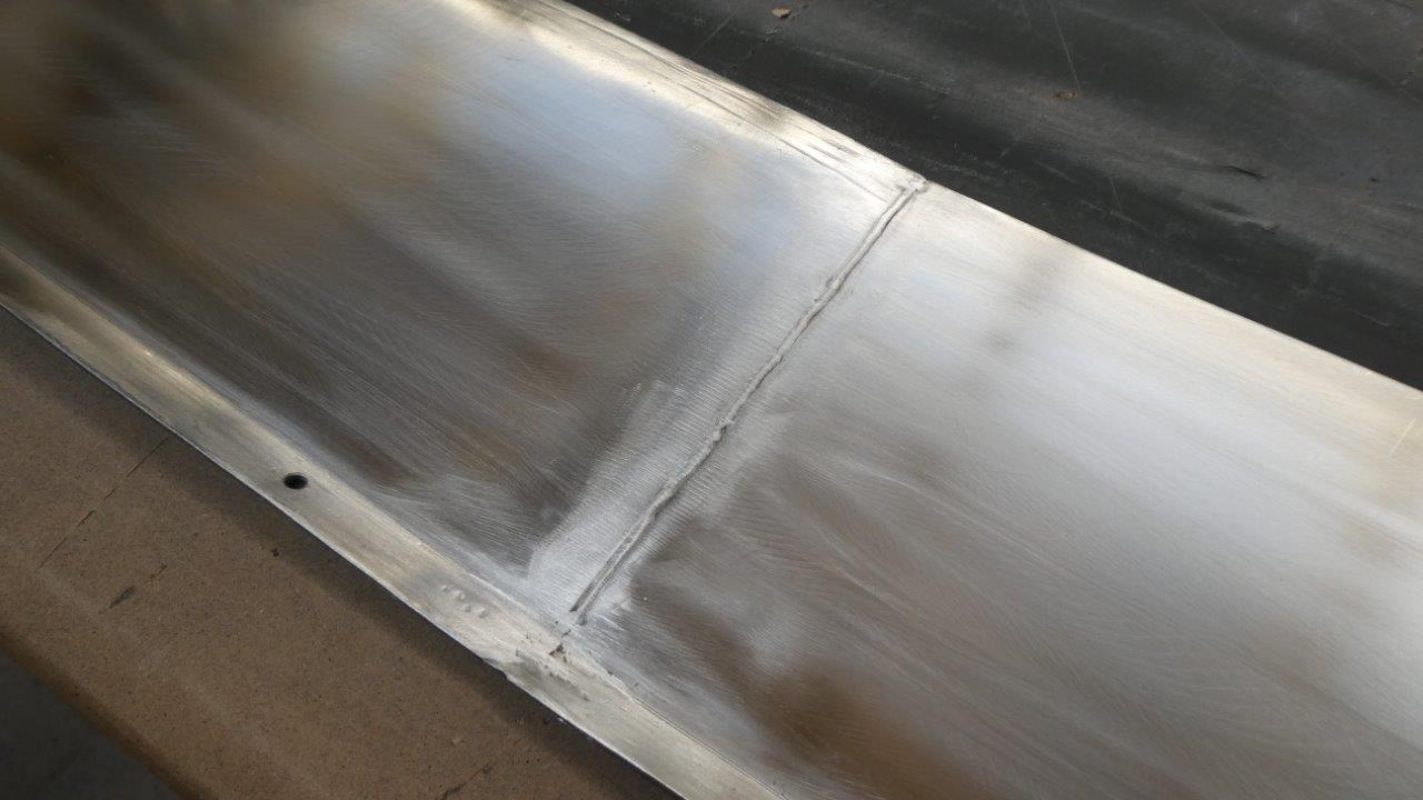
While both halves were held in place I ran the laser straight down the join. This is what it looks like after a strip disc has run over it as was getting it ready for paint. I have not had to planish it at all.
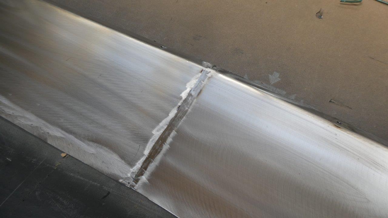
The underside had a quick pass with the flap disc over the penetration just to clean it up ready for paint.
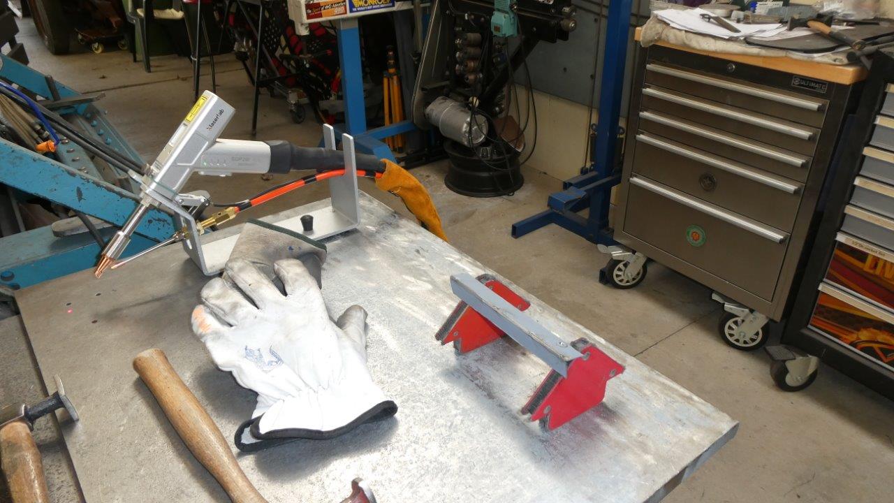
I am doing a mock up of the angles the new panels sit in relation to the upper support. I want to see if I can just fuse weld the two together without any wire. I just have the new panels sitting directly on top of the supports. To make this weld easier I switched out the CS-12 welding nozzle, which is for butt and inside corner fillet welds, for the ES-12 nozzle which has two side prongs that help you steady the gun on both surfaces. Even though this weld is without wire, I found it better than the dedicated corner fuse nozzle. The -12 means the wire guide groove is for up to 1.2mm wire. There is another set of -16 nozzles which is for 1.6mm wire.
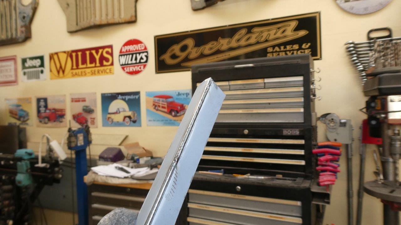
I do like this ES-12 nozzle more and it works well with butt welds too, so will use it more as I can see the join and weld better as I am moving along. I did have to move the focus tube in more from the factory set +4mm down to +1mm as the nozzle holds the gun away from the surface that much more. To set the focus you loosen the tube nut and start with it all the way in. Fire the laser on some thick plate, and while holding the nozzle on the plate, pull the gun back slowly until it makes the most noise and sparks. You will probably go and bit pass and see and hear it change the other way, so you slide back down to where it is the most aggressive. This is what the fuse weld came out like, on the bench at least.
As there is no wire to help you with travel speed, you can see my tacks were deeper than the rest of the weld in the penetration. I will slow my speed down once I weld on the car.
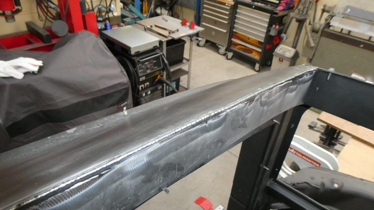
I welded the full 2 metres or 6 1/2 feet each side. Was not as smooth as the test piece as I was hanging with one hand to hold on for balance, while welding with the other.
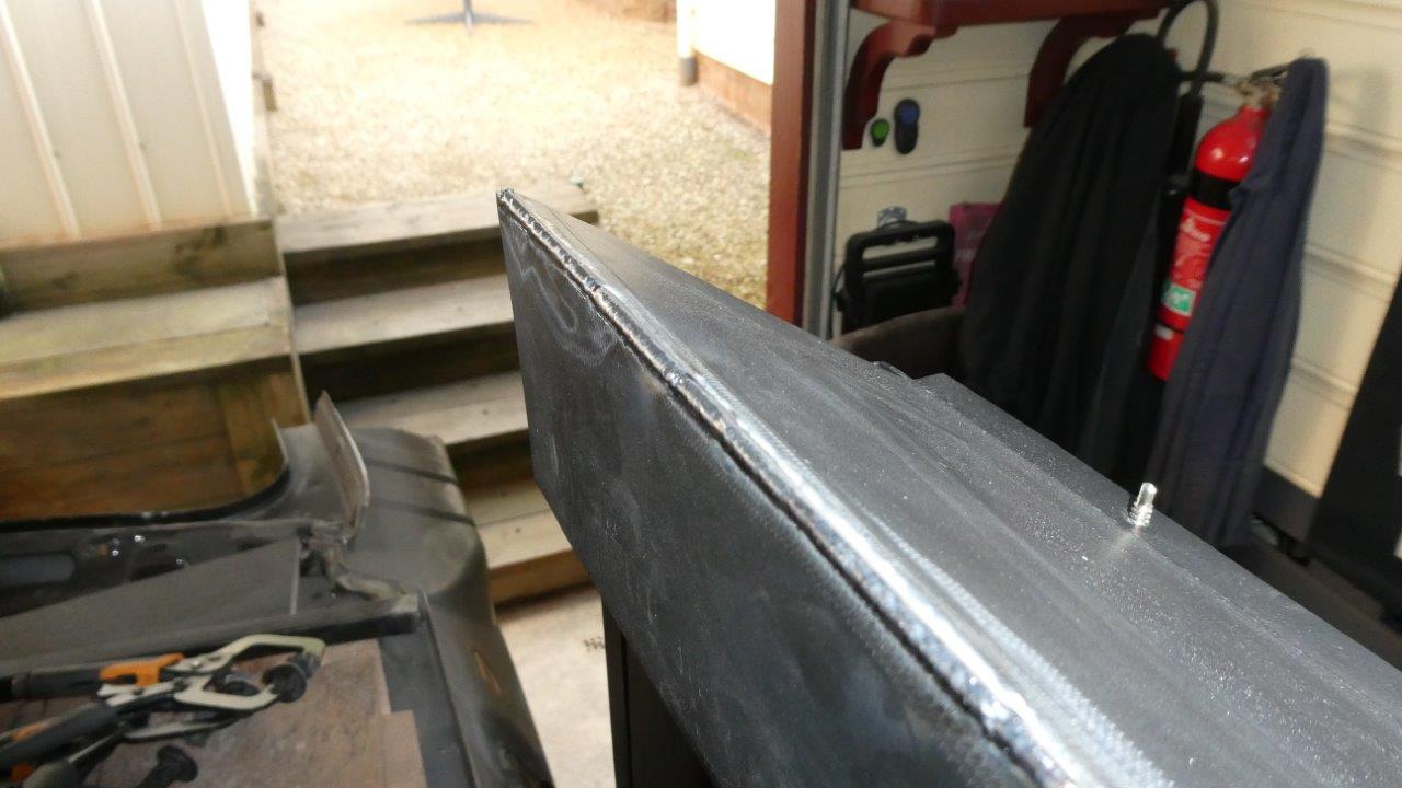
I got good penetration all the way through to the other side. You get much less paint burn off too with the laser compared to the TIG. They report welding speed is up to 5 times faster than TIG and it feels every part of that!
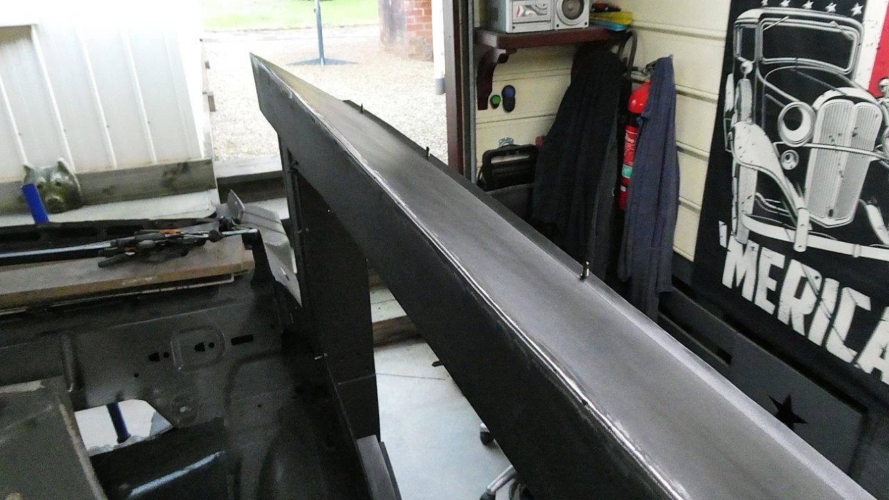
I just passed a flap disc quickly over each surface and another pass to round it and I was done. Look how little distortion there is. There was already some from just bending the panel over my knee and looks even better now!
I am so far really pleased with the process of laser welding and it is everything I hoped it would be. Things have really sped up and my body is liking the reduction in hammering which means I can keep going on the project without stopping for recovery breaks away from the workshop. Lets hope it stays reliable, but have seen minor issues fixed without needing a technician when the company just sent out a replacement part with instructions on how to change it themselves.
I would also look up Brent on Halfass Kustoms on YouTube as he has done nearly a year of welding with his X1 Pro and is very hard on it with dirty rusty steel with gaps and all!
Also there are a lot of destruction videos out there testing the welds from hand held lasers, but like this one the most put out by Sylvester Customs as relates to what I am using it for and has the same techniques for the TIG and MIG as I do in the tests.
https://www.youtube.com/watch?v=AhoroUvWiTw&list=LL&index=4&t=940s&pp=iAQBsAgC
All the major European car manufacturers as well as GM, Ford and Chrysler use robotic lasers on the production lines, so great to see it brought down to a home workshop level.
Video update on most of the build.