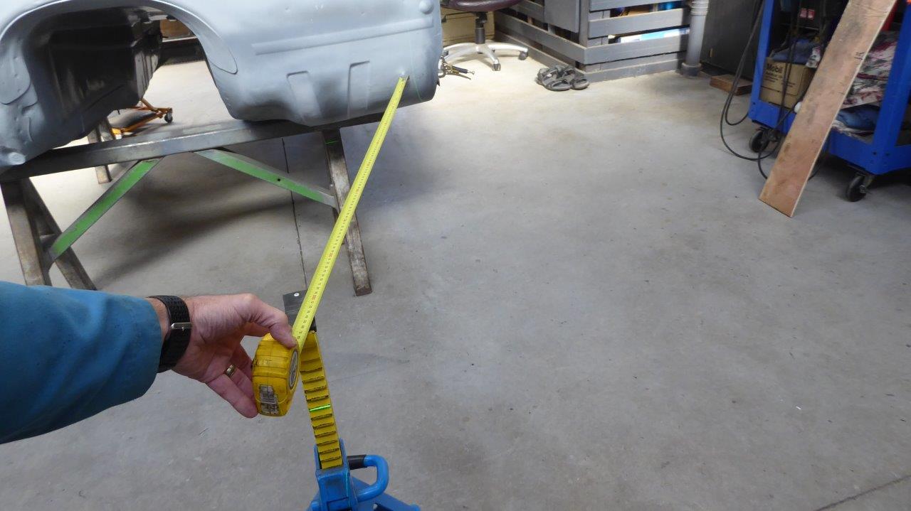
I needed to check to see if I could run straight from the side of the grille to the A pillar, the line that the hood/bonnet sides will take. So I placed an axle stand where the edge of the grille would be once widened and then projected a laser line to the outside of where the A pillar will end up. That line runs down the outside of the tape measure and shows how much of the firewall is too wide!
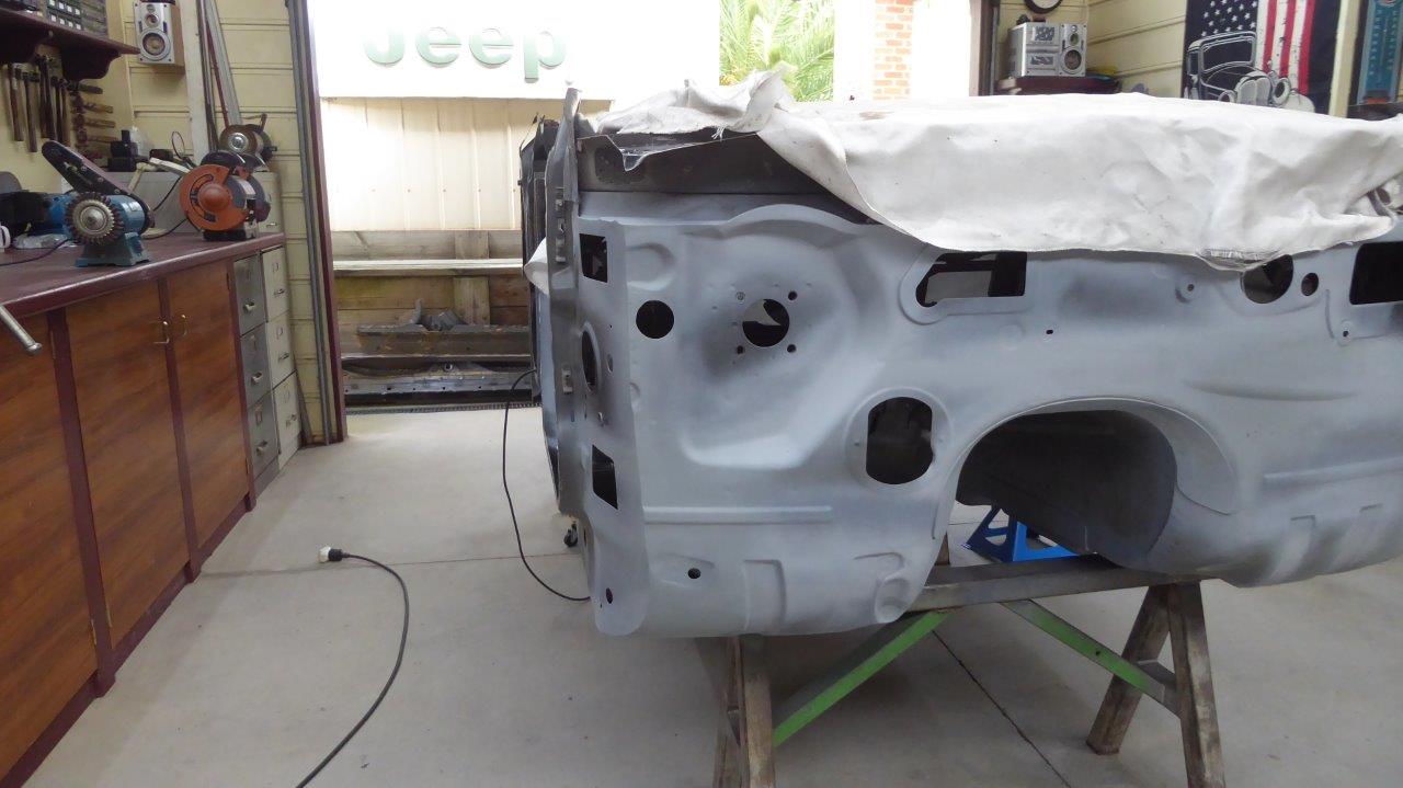
If I cut the firewall straight up from that line I wouldn't even be able to fit the A/C unit back in on the passenger side, or mount the drive by wire throttle pedal on the drivers. That is when I realised that only the bottom part has to be that far in, from just above the chassis rail, and from there up it just has to follow the shape of the door skin. Here you can see how it curves up now, getting wider at the top. I can now just get in the A/C unit in on this side.
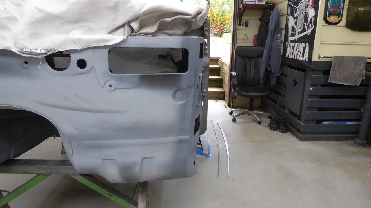
Here you can see both the modified passenger side along with the drivers side marked out ready to be cut the same.
Here is how I went about it. First the firewall was cut free from the cowl side and then the section removed from the firewall. Then a relief cut was made where the lower part of the body steps in as this will need to be able to compress once the bending takes place. A ratchet strap pulling over some angle iron, to keep it even, was used to pull the cowl across to the narrowed firewall and then a bolster was hit from the inside along where I wanted it to bend form. The gap left is due to the firewall being curved across the front.
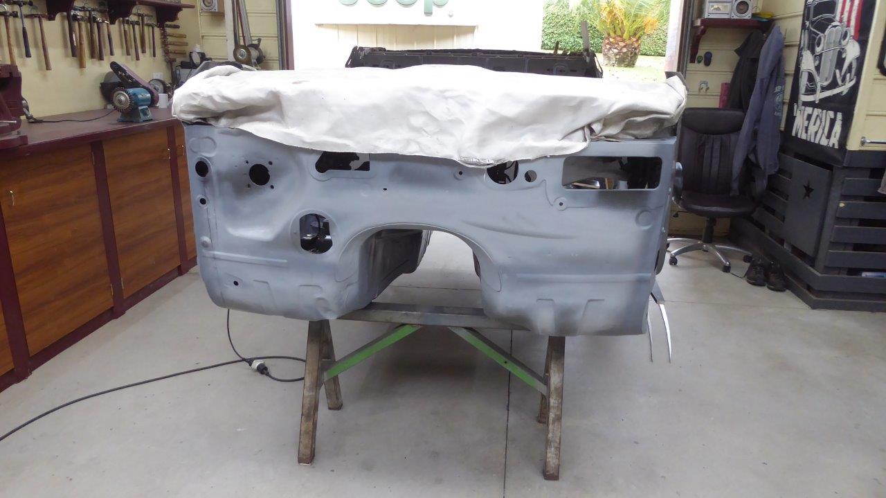
The cowl side was extended to meet the firewall once more using matching steel from the door sill that had been removed earlier. The hole for the wiring harness was moved across and the drive by wire throttle pedal still fits onto the inside of the firewall on the stock mount.
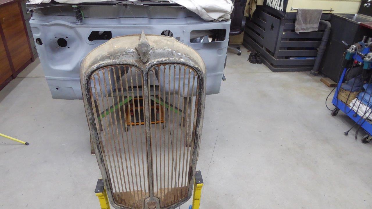
I set the grille up off centre so the passenger side is where it will be once widened later on to get more of a visual. The black line on the floor shows the line that the hood/bonnet side will take to the A pillar. I may run a slight curve to it yet, but that will be decided later on depending if I need to clear the side of the HEMI.
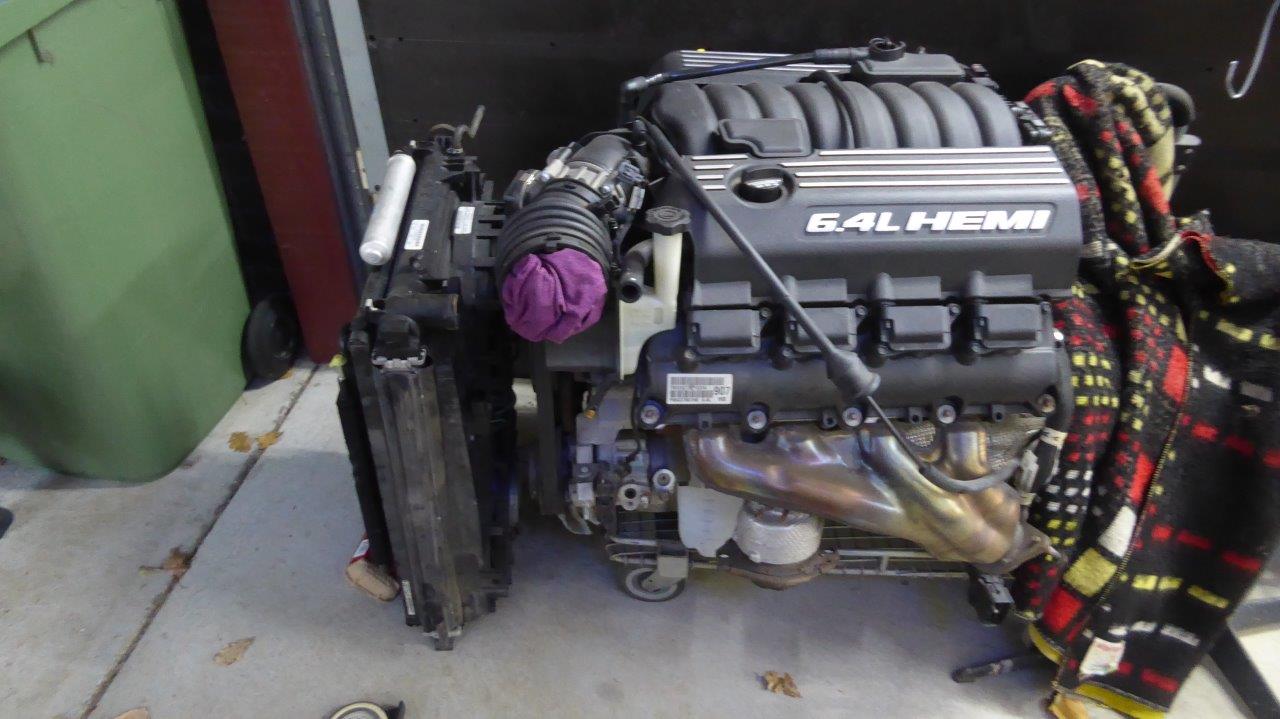
Narrowing the firewall reminded me just how much the firewall is curved. I had made a note of it that it was 84mm/3.3" closer to the grille in the middle than the sides. But did I remember to take that into account when calculating the engine bay length needed for the the engine and radiator/fan etc to fit in? I'm already moving it as close to the firewall as it can go, 140mm-5.5" closer than factory, but suddenly thought I was measuring from the side of the cowl and not the middle of the firewall! Only one way to find out and that was to sit the radiator, condenser and fan combination in front of the engine the same distance from it as it was installed in the donor engine bay. I remember it already being very tight but did have it all written down. Above shows it with the only difference being that I have turned the radiator 90 degrees so it will fit inside the Willys grille. This is no problem for the radiator to run that way as this was quite normal until cars had lower frontal area and had to run cross flow radiators instead. However you cannot do this with the A/C condenser as the tubes must remain horizontal for the gas to return back into a liquid state efficiently. So a taller and narrower condenser will replace the stock one later on.
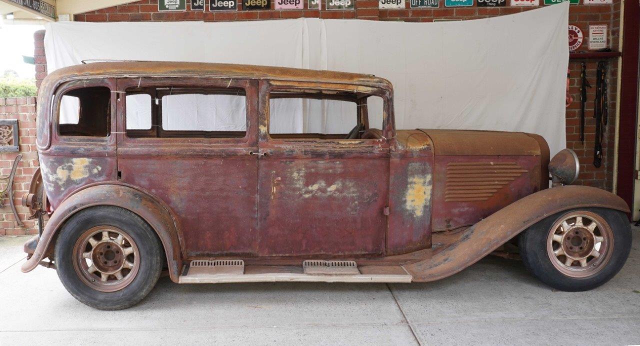
Turns out that I did not have enough engine bay length after all, and I knew I was already a bit short even measuring from the side of the firewall. So looks like an extra 100mm/4" will be needed to fit everything in, and that is with the condenser/radiator/fan unit inside the grille shell as much as possible. Just as well I have already shortened the body as much as practical, otherwise the car would be awfully long! Least it wont look snub nosed now with the longer than stock body behind it. More in keeping with the big luxury cars of the era now too.
Another thing I have also established is that the engineer is happy with my plans to stitch weld the Willys original chassis rails top and bottom directly to the sides of the body making it into a unibody instead of hard bolting it to the chassis as was stock. He also inspected and approved using the donor unibody frame over the rear independent suspension, using all its mounting locations, before the Willys rails are then used the rest of the way again. They will also run all the way to the very front of the car as well holding the engine and front suspension in place.
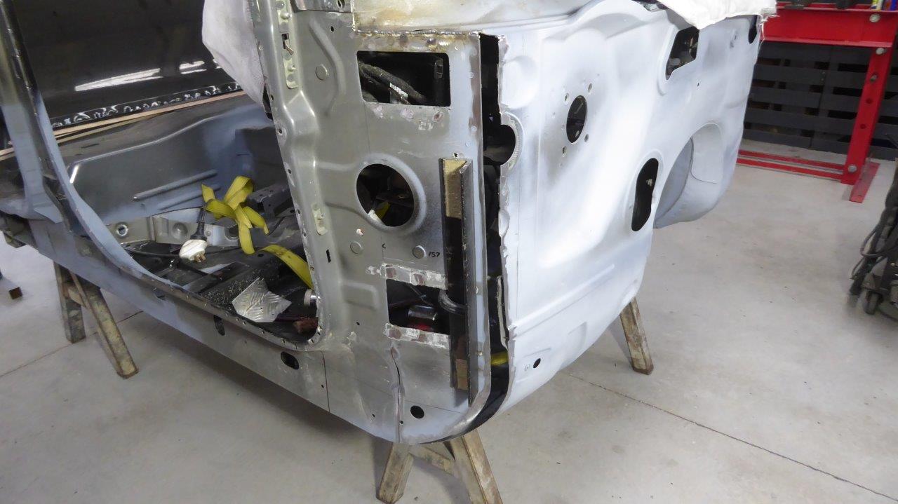
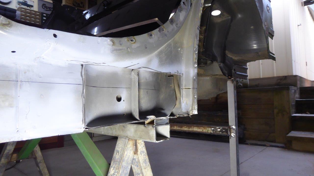
The connection between the two will use the factory donor stiffening brace that runs up inside the rear frame pressing. This was not connected to the outer sill before. I have trimmed it back the thickness of the boxing plate I'm going to add so it will be flush with the rest of the inner door sill.
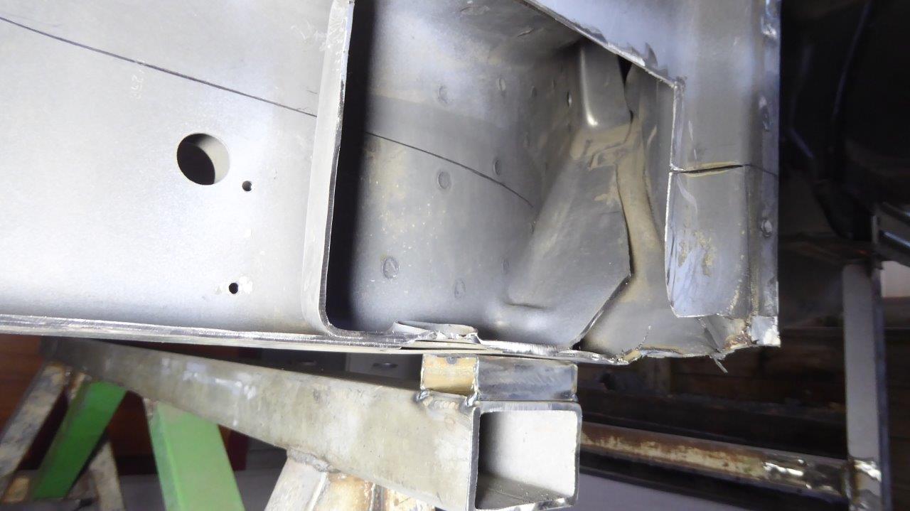
For the first time new steel is being added to the body that was not from the left over donor shell! I have folded this plate up with slots cut into it that line up with the ends of the inner brace. The inside was etch primed and weld through zinc coating added as it wont be able to get to later on.
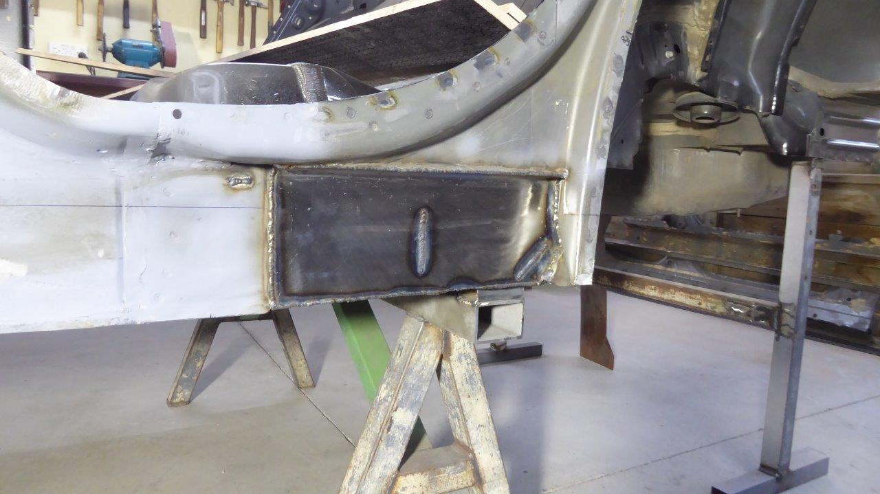
It was fully welded around the sides and through the slots onto the inner brace to make it one unit. The black line shows where the top of the chassis rails will be once fitted leaving enough room to weld the top of the chassis to the plate.
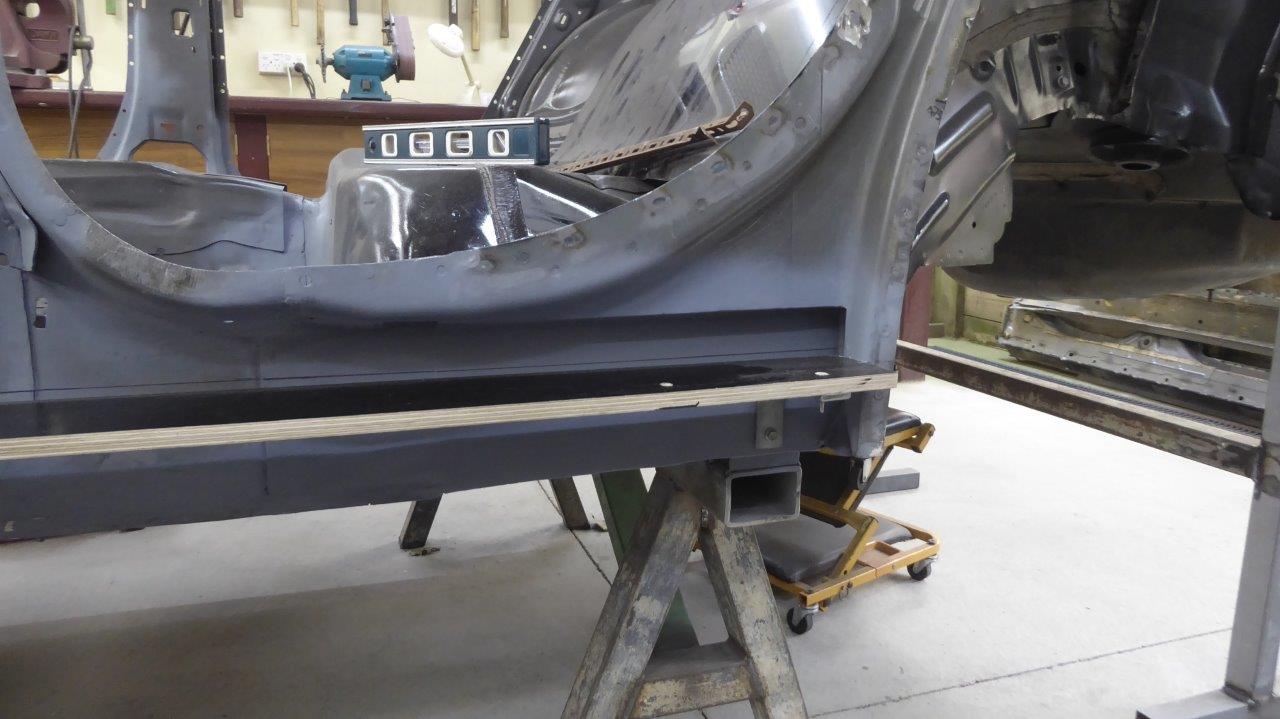
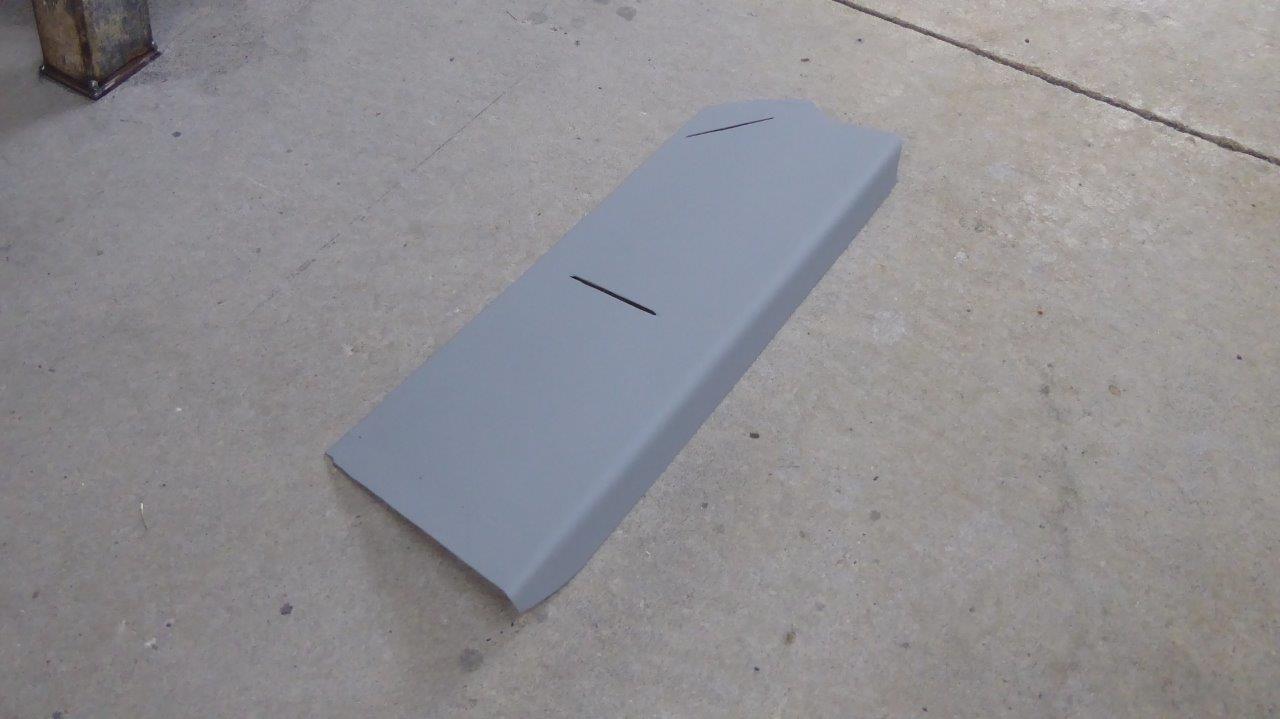
The top of the ply, that I am using for the body curve template, is at the height that the chassis rails from the Willys will sit at.
I have mocked up the B pillar into position and notice how far out the angle of the top of it is due to angling the lower pillar forward until it is vertical. Another thing I was working out was angle of the window sill line. The stock Willys only has 0.5° of slope but the donor Chrysler had 2°. I had to raise the front and lower the rear at the parcel shelf just to get down to that number due to it becoming steeper after shortening the body length.
If I went for that extra 1.5° over stock, would there still be enough height to fit the grille in without cutting it down? Turns out there will be so that is not a problem.

But what would it look like? Above is the stock mock up with approximately the extra length I have to put in the doors to fit the shortened donor shell.
This is with the angle added and it is around 2° total.
Originally the thought was to add to the bottom of the doors as well to help the window height to lower door ratio.
But then once you add the extra angle to that, it looks like it might too much?
With the increased window sill angle, maybe only 50mm/2" extra would be all that is needed? I don't want it looking too heavy either.
What is not in the other mock ups is the fact that the whole rear wheel arch has to be raised 50mm/2" as well, bringing that distance between the top of the arch and the beltline back to what it was before the wedge was added. Above that has been done along with the extra 50mm/2" door extension from the photo before.