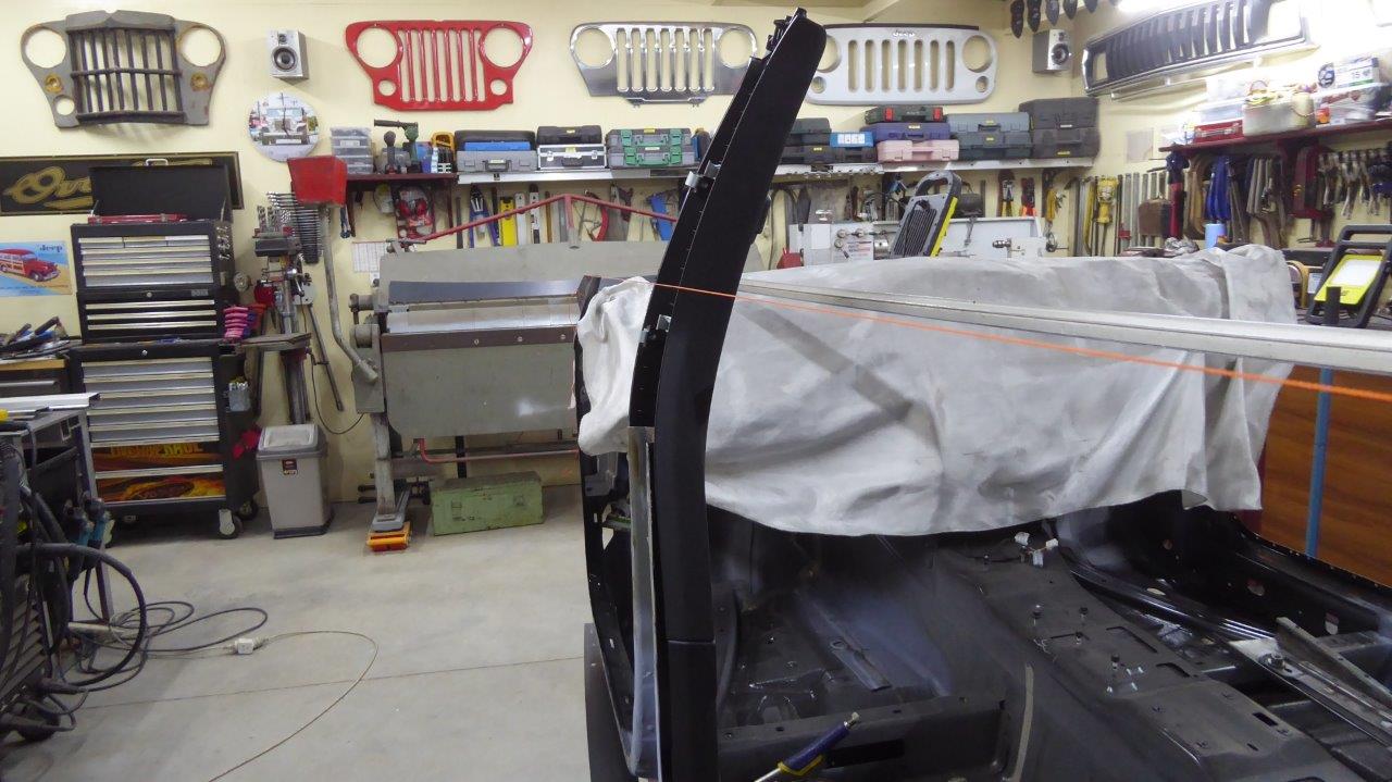
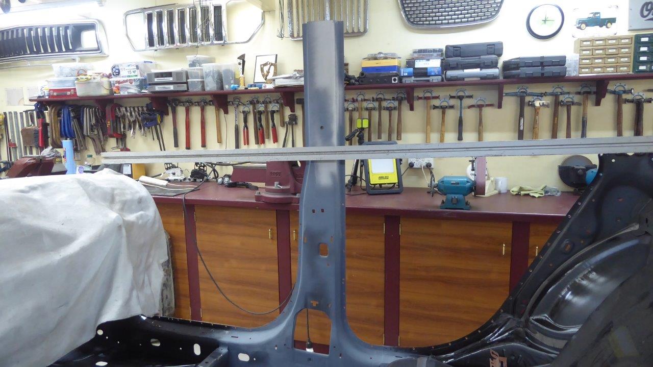
Back to working on the upper B pillar. Look how much the donor Chrysler leaned inwards! You can see why I chose to cut the B pillar off where I did, just before the bend. I'm still hoping I can use the plastic interior trim throughout right up to the window sill line which is where the orange string is.
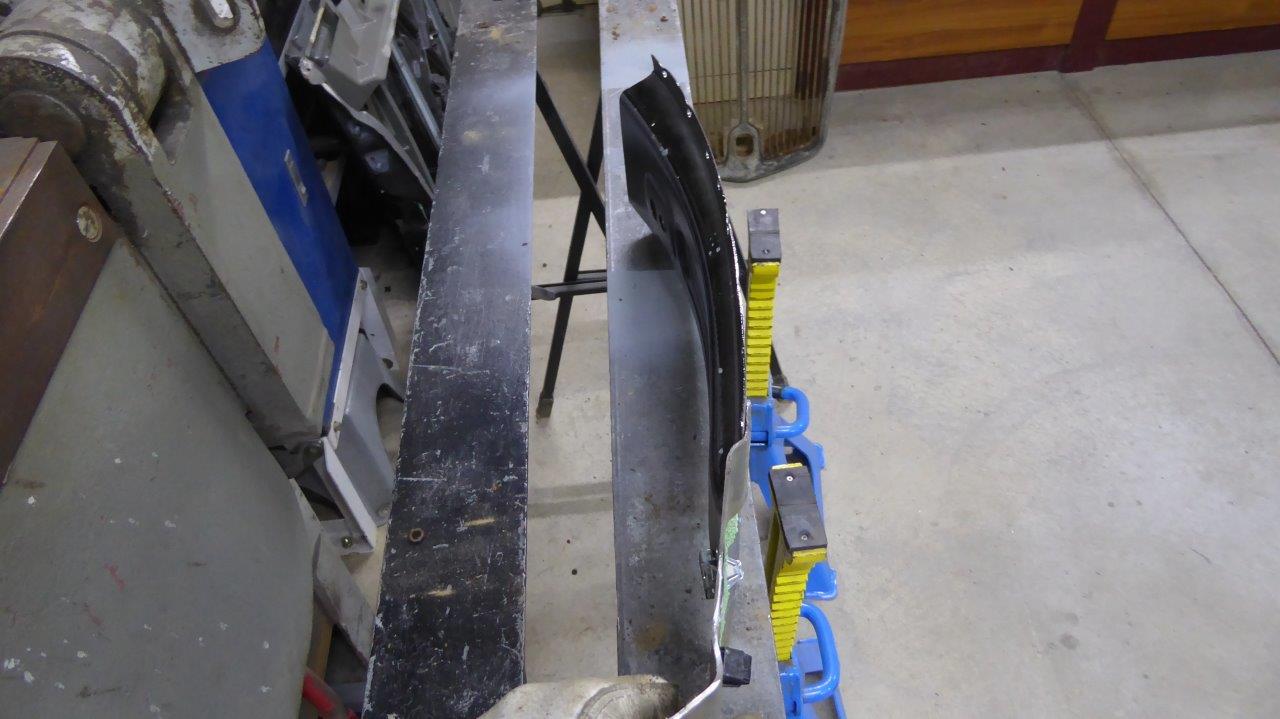
This is the inner half of the steel pillar that I had saved after cutting it off. I thought it would be a good challenge for some reason to see if I could straighten it by mainly stretching.
I was successful, but it took way too much time. Then had to add length back to it after cutting off the angled top part as well as add some width to match the doors between the windows.
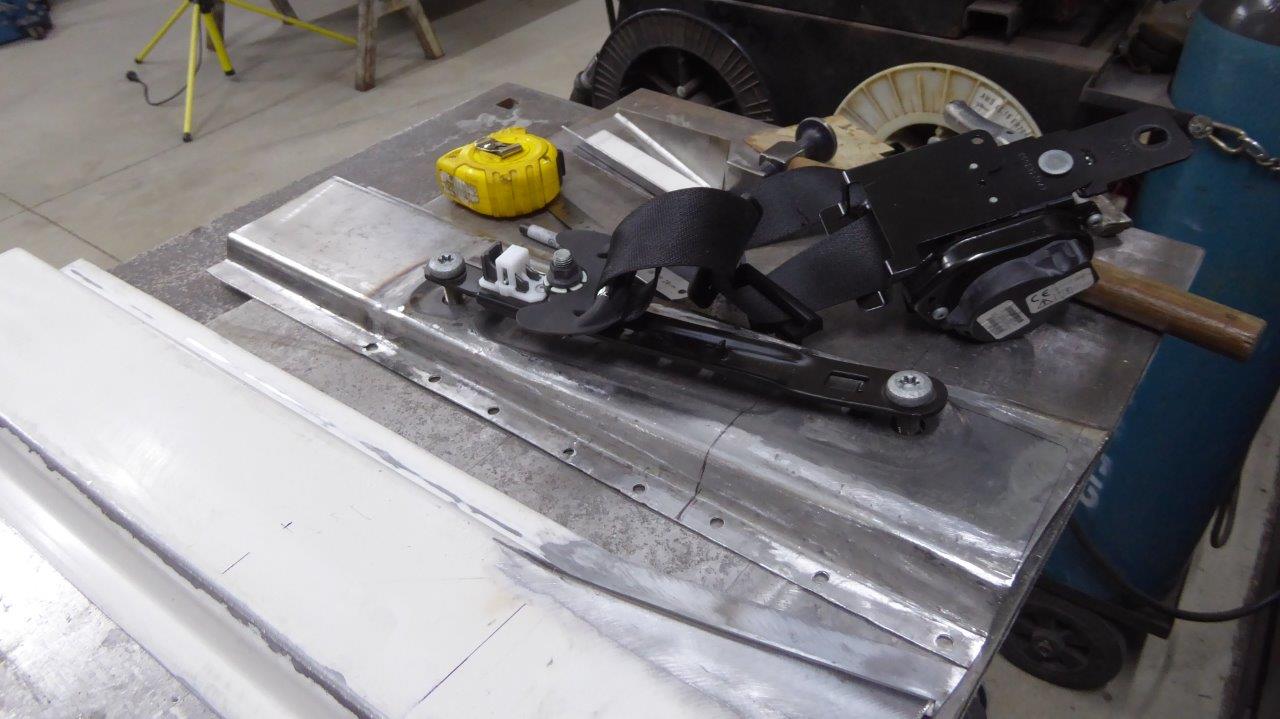
Then I added the top mount seat belt adjustor after straightening that out to fit as well. Then stood back and thought, I have never ever adjusted that in my life as it is always at the top! The pillar also narrows to give more headroom for the inward tilt that I have just removed as well!
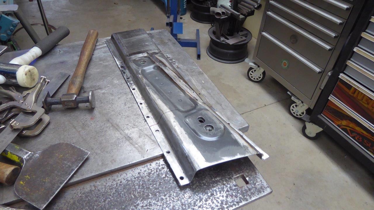
So I scrapped it all and made a new piece from scratch that doesn't taper and has just a fixed upper belt mount. Oh well, it was good practice to see what could be reshaped if needed. The overall height is right to the top of the roof skin so will be cut down exactly later on. Rather have more than needed to work with.
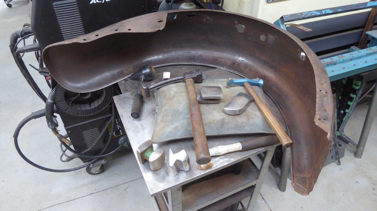
Before I can build the rear door, I need to know where the rear guard/fender is going to sit. To make sure it is as accurate as possible, any repairs and modifications need to take place to it first. It had gathered some damage in its 93 year life so far, including being a paddock basher and garden art for the last half of it. Here I am knocking out the main dents and creases using the hammers and dollies shown over the sand bag.
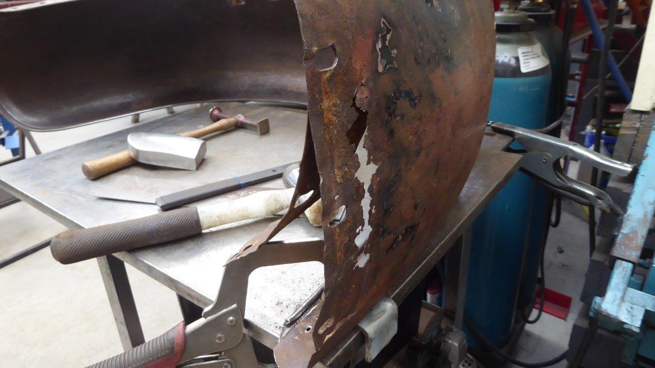
A lot of rust also where the inner brace is and where it bolted to the running board. I made a quick patch for that and tacked it in place just so it could hold some shape.
It had a number of flat areas on the edge as well for some reason and not a consistent curve that the other side has. I have already repaired one such area above this, but thought I would show how I went about putting curve into the edge which has 4mm-5/32" wire inside of it. First I would cut a eyebrow shaped slot just behind the edge bead as pictured.
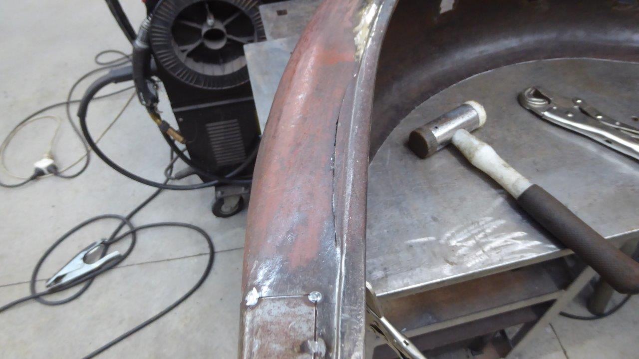
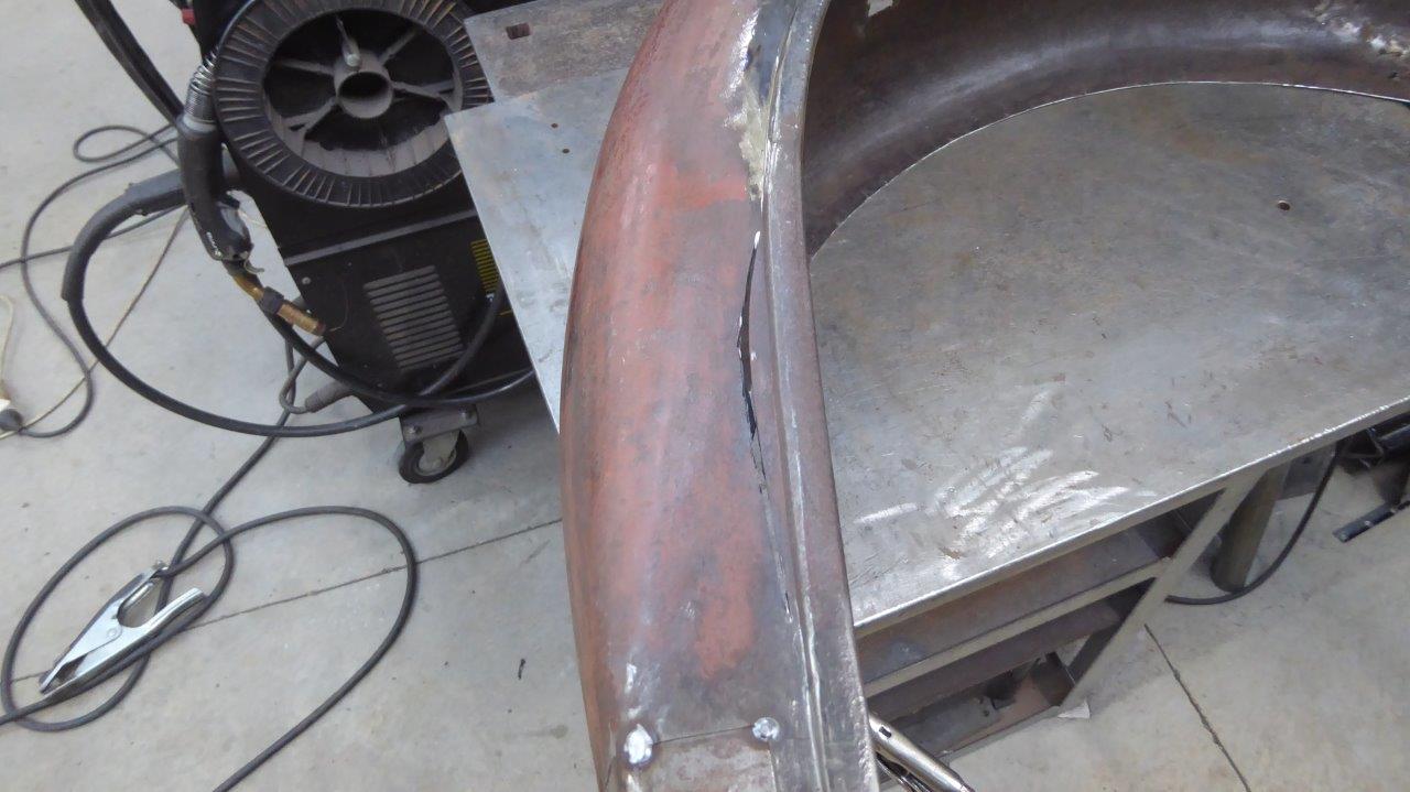
Next I would use a soft hammer to hit it across supporting the outside of the guard with my hand. If there was not enough curve yet, I would cut more away before repeating the exercise. The edge would twist, so it is important to twist it straight again using channel grips or pliers before moving on.
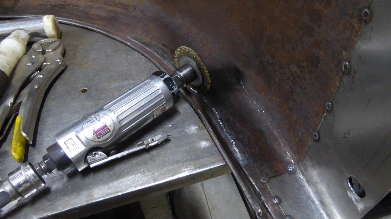
Once I was happy with the curve, or I couldn't get it to move anymore, I welded up the slot. This is the method I use to cut the top off the weld. A die grinder with what is left from a 9" cut off wheel! The disc was first used in my 9" grinder until it wore down to 5". It was then used in my 5" grinder until it was too small for that. Then it gets used in the die grinder until it is down to the support rings. The grinding is done at an angle to the weld only touching the weld surface, and not the original metal.
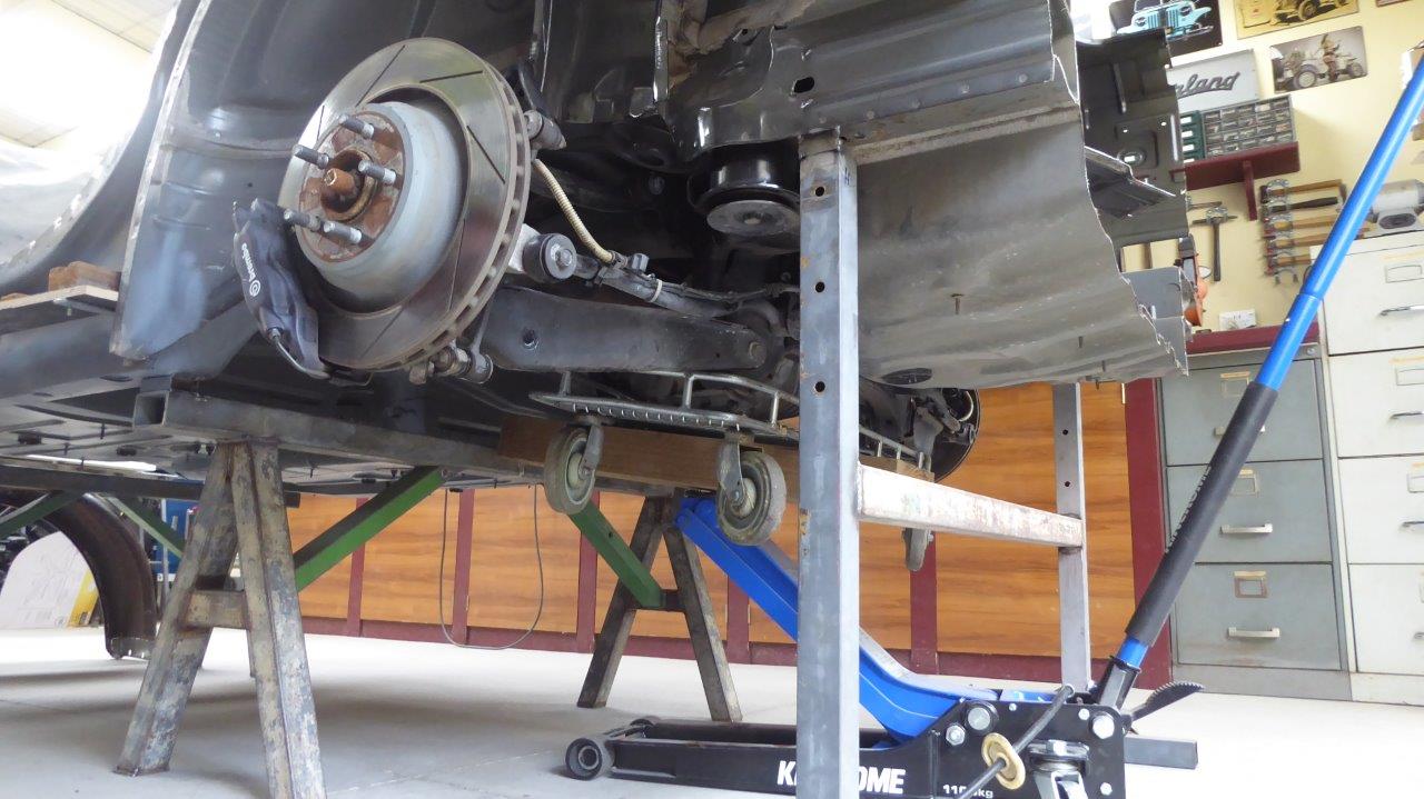
To make sure I had the exact centreline of the axle, I first put it back into place. Being on my own it would be awkward to first remove the assembly from the trolley it was on, and then get a jack perfectly balanced under it. So I put a piece of 8"x3" timber on the jack and rolled that under the trolley and jacked up the whole thing as one! Put the four bolts in and lowered the jack and trolley back down and the job was done.
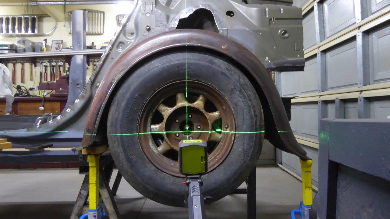
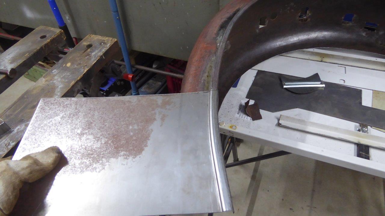
I used the laser making sure it was, not only exactly on the axle centre, but also square the the body as well. Otherwise on a multi-depth surface it will not read accurately at all. I placed the Willys guard in place and lifted it until it was at the same height as where the inner wheel well liner sits on the donor Chrysler. This will make sure I will have the same amount of up travel on the suspension without it hitting the guard. This places the guard 60mm-2 3/8" higher in the body than stock. So the whole wheel tub and arch in the Willys body will have to be lifted as well on the rear quarter panel.
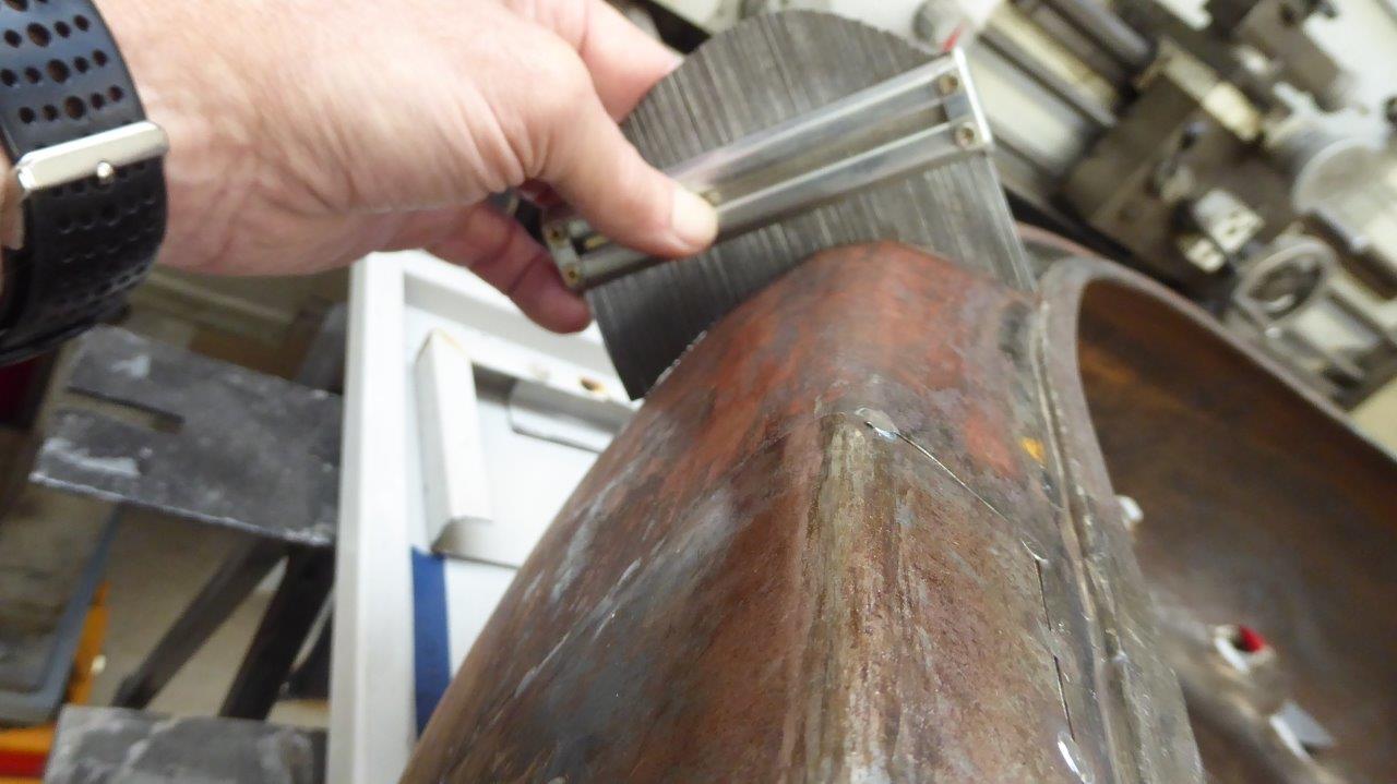
The guard will also have to be made longer to suit the higher mounting position. So rather than cut and add to the guard at both ends to make it longer, I just rotated the guard around until it started at the same spot in the body as stock. I will then just add twice as much to the start of the guard where the shape is simpler as well. The start of the guard however does have a transition from flat, where it attaches to the running board, into the curve profile it has from the rest of it. The contour gauge is showing the profile further up the guard where the transition starts.
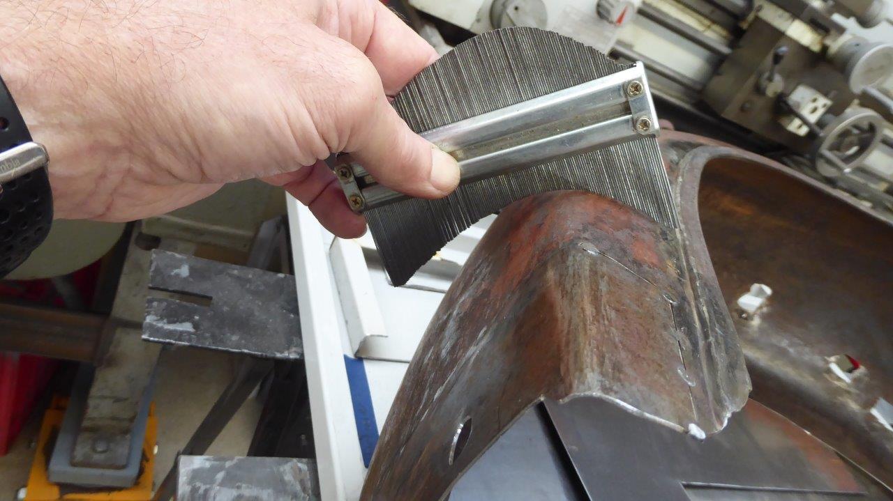
This is how much it has changed in the distance the extension needs to be. I don't want to just extend the flat section of the end to make up the length, as that just wouldn't look right.
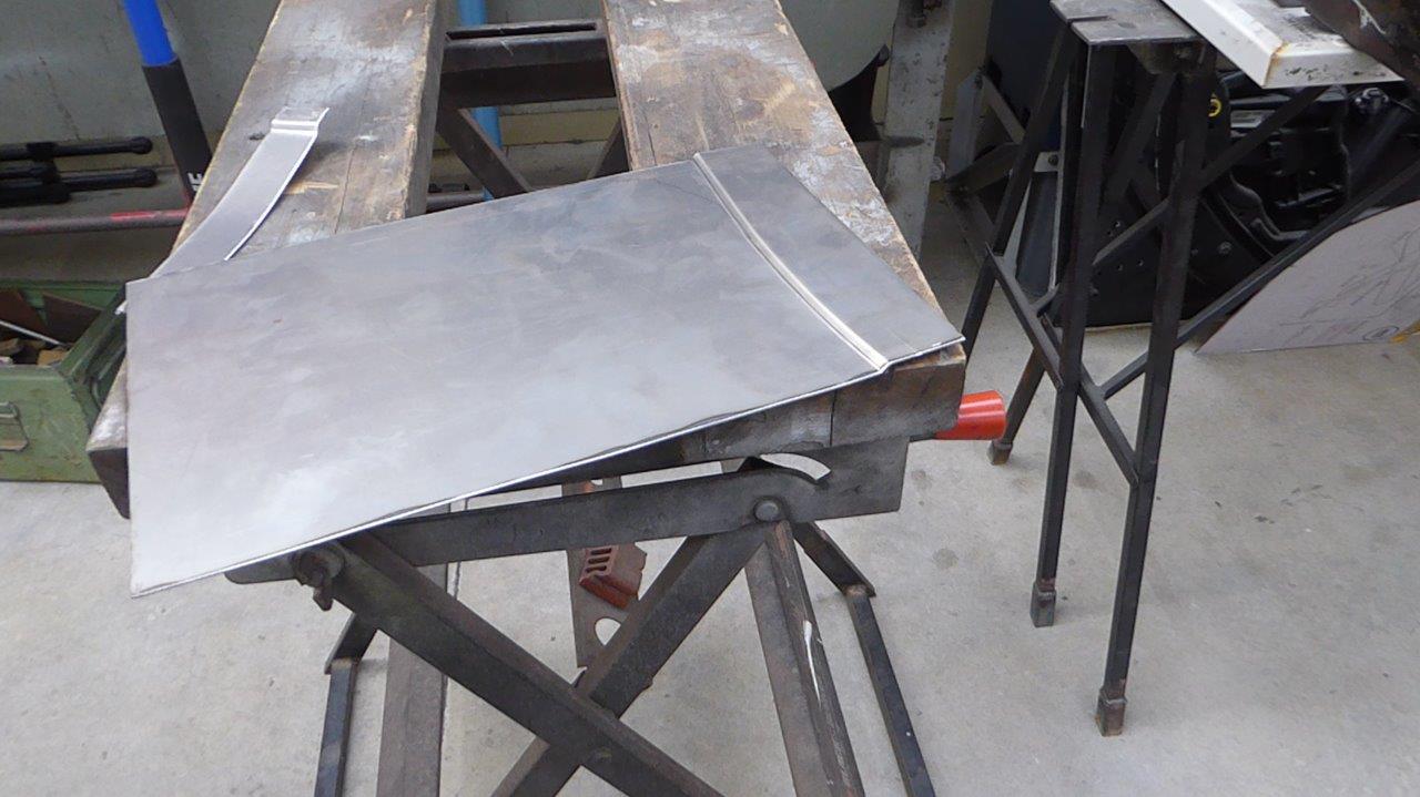
I am making the new piece big enough to replace the rusted section as well as the extra length needed to account for sitting higher up in the body. I used a step die in my bead roller the same height and offset as the edge bead. This just gives me the first bit of the edge profile.
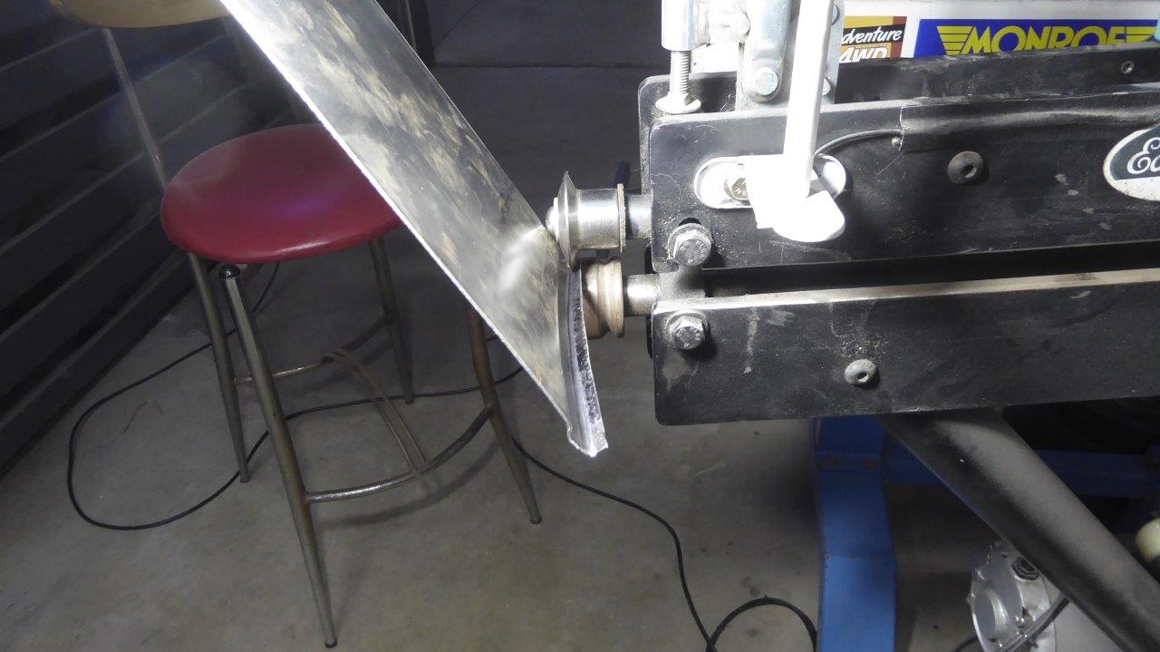
The start of the wire edge was next and I started that by using a tipping die to form a 90° fold. As the edge is curved, I cannot not do this in a folder.
I have a pretty good match to the edge bead, although slightly wider, but that can be tighten up later when the edge will be rolled around the wire.
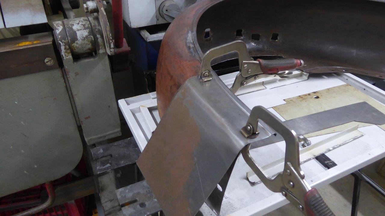
To start the shape of the piece I clamped it to the guard and just pulled it around by hand over the section of the transition.
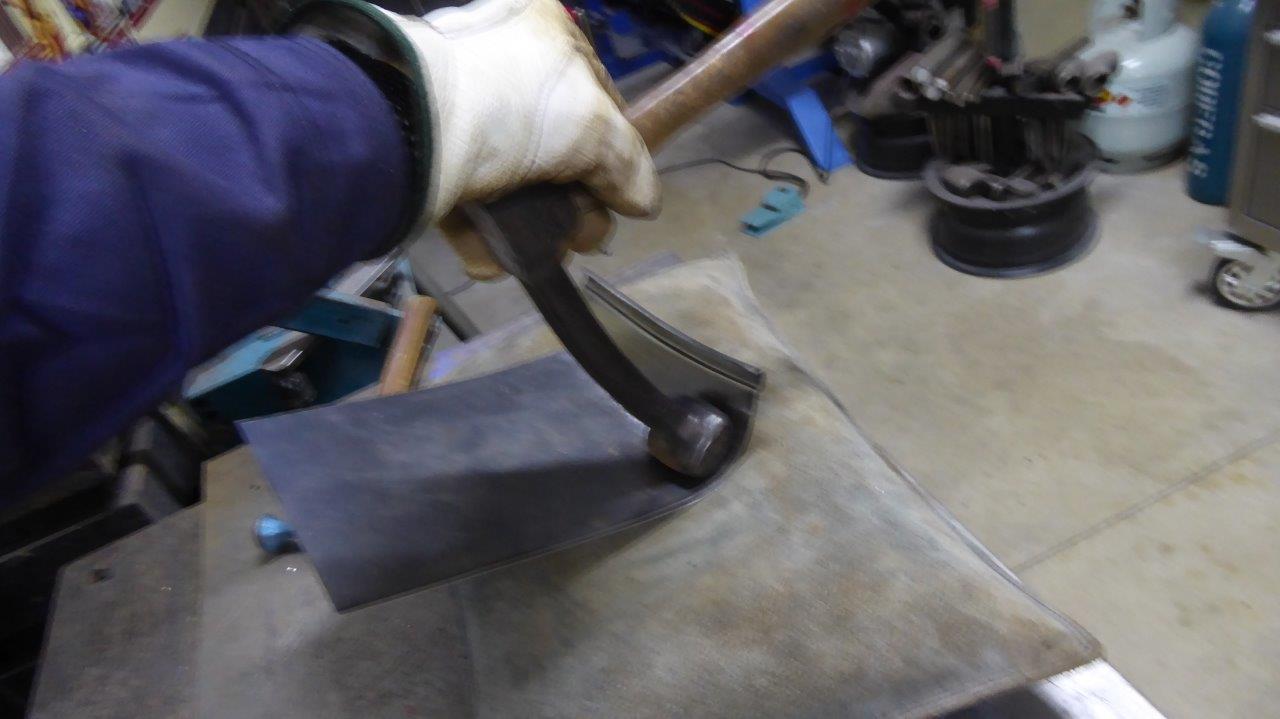
Over the sand bag I used this huge antique fender hammer to form the wide end of the radius.
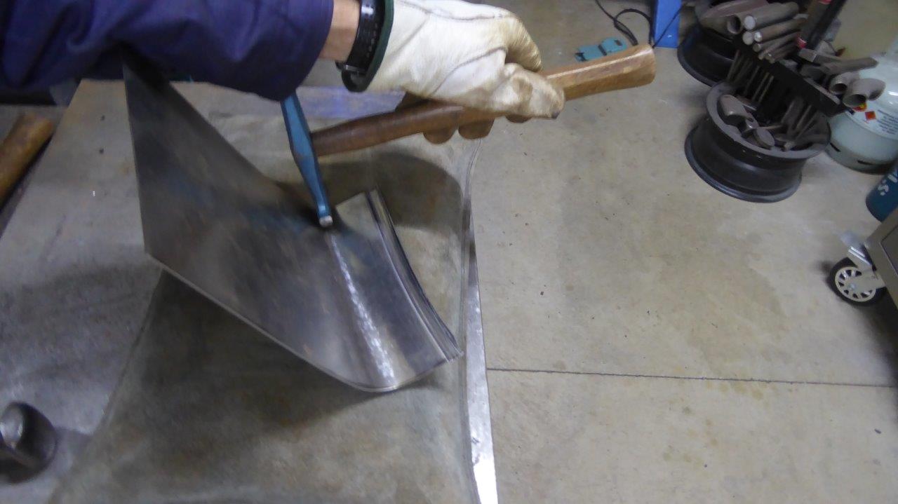
Then used a quality hammer I got from Peter Tommasini at Hand Built Tools who were just around the corner from me. He has always been a great supporter of mine with advice and encouragement.